Amplifier with three KT315 transistors. Simple circuits on KT315. Track-cascade ULF with direct coupling
Low frequency amplifiers (LF) are used to convert weak signals predominantly in the audio range into more powerful signals acceptable for direct perception through electrodynamic or other sound emitters.
Note that high-frequency amplifiers up to frequencies of 10... 100 MHz are built according to similar circuits; the difference most often comes down to the fact that the capacitance values of the capacitors of such amplifiers decrease as many times as the frequency of the high-frequency signal exceeds the frequency of the low-frequency one.
A simple amplifier with one transistor
The simplest ULF, made according to a circuit with a common emitter, is shown in Fig. 1. A telephone capsule is used as a load. The permissible supply voltage for this amplifier is 3...12 V.
It is advisable to determine the value of the bias resistor R1 (tens of kOhms) experimentally, since its optimal value depends on the supply voltage of the amplifier, the resistance of the telephone capsule, and the transmission coefficient of a particular transistor.
Rice. 1. Circuit of a simple ULF on one transistor + capacitor and resistor.
To select the initial value of resistor R1, it should be taken into account that its value should be approximately one hundred or more times greater than the resistance included in the load circuit. To select a bias resistor, it is recommended to connect in series constant resistor with a resistance of 20...30 kOhm and a variable resistance of 100...1000 kOhm, after which, by applying a small amplitude audio signal to the input of the amplifier, for example, from a tape recorder or player, by rotating the variable resistor knob to achieve best quality signal at its highest volume.
The capacitance value of the transition capacitor C1 (Fig. 1) can range from 1 to 100 μF: the larger the value of this capacitance, the lower frequencies the ULF can amplify. To master the amplification technique low frequencies It is recommended to experiment with the selection of element values and operating modes of amplifiers (Fig. 1 - 4).
Improved single-transistor amplifier options
More complicated and improved compared to the diagram in Fig. 1 amplifier circuits are shown in Fig. 2 and 3. In the diagram in Fig. 2 amplification stage additionally contains a chain of frequency-dependent negative feedback(resistor R2 and capacitor C2), improving signal quality.

Rice. 2. Diagram of a single-transistor ULF with a chain of frequency-dependent negative feedback.

Rice. 3. Single-transistor amplifier with a divider to supply bias voltage to the base of the transistor.

Rice. 4. Single-transistor amplifier with automatic bias setting for the transistor base.
In the diagram in Fig. 3, the bias to the base of the transistor is set more “rigidly” using a divider, which improves the quality of operation of the amplifier when its operating conditions change. “Automatic” bias setting based on an amplifying transistor is used in the circuit in Fig. 4.
Two-stage transistor amplifier
By connecting two simple amplification stages in series (Fig. 1), you can obtain a two-stage ULF (Fig. 5). The gain of such an amplifier is equal to the product of the gain factors of individual stages. However, it is not easy to obtain a large stable gain with a subsequent increase in the number of stages: the amplifier will most likely self-excite.

Rice. 5. Circuit of a simple two-stage low-frequency amplifier.
New developments of low-frequency amplifiers, the diagrams of which are often given on the pages of magazines recent years, pursue the goal of achieving a minimum nonlinear distortion factor, increasing output power, expanding the amplified frequency band, etc.
At the same time, during setup various devices and conducting experiments, you often need a simple ULF, which can be assembled in a few minutes. Such an amplifier must contain a minimum number of scarce elements and operate over a wide range of changes in supply voltage and load resistance.
ULF circuit based on field-effect and silicon transistors
The circuit of a simple low-frequency power amplifier with direct coupling between stages is shown in Fig. 6 [Rl 3/00-14]. The input impedance of the amplifier is determined by the rating of potentiometer R1 and can vary from hundreds of ohms to tens of megohms. You can connect a load with a resistance from 2...4 to 64 Ohms and higher to the amplifier output.
For high-resistance loads, the KT315 transistor can be used as VT2. The amplifier is operational in the range of supply voltages from 3 to 15 V, although its acceptable performance is maintained even when the supply voltage is reduced to 0.6 V.
The capacitance of capacitor C1 can be selected in the range from 1 to 100 μF. In the latter case (C1 = 100 μF), the ULF can operate in the frequency band from 50 Hz to 200 kHz and higher.

Rice. 6. Scheme simple amplifier low frequency on two transistors.
The amplitude of the ULF input signal should not exceed 0.5...0.7 V. The output power of the amplifier can vary from tens of mW to units of W depending on the load resistance and the magnitude of the supply voltage.
Setting up the amplifier consists of selecting resistors R2 and R3. With their help, the voltage at the drain of transistor VT1 is set equal to 50...60% of the power source voltage. Transistor VT2 must be installed on a heat sink plate (radiator).
Track-cascade ULF with direct coupling
In Fig. Figure 7 shows a diagram of another seemingly simple ULF with direct connections between cascades. This kind of communication improves frequency characteristics amplifier in the low-frequency region, the circuit as a whole is simplified.
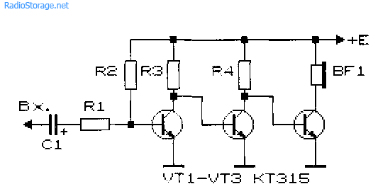
Rice. 7. Schematic diagram of a three-stage ULF with direct connection between stages.
At the same time, tuning the amplifier is complicated by the fact that each amplifier resistance has to be selected individually. Approximately the ratio of resistors R2 and R3, R3 and R4, R4 and R BF should be in the range (30...50) to 1. Resistor R1 should be 0.1...2 kOhm. Calculation of the amplifier shown in Fig. 7 can be found in the literature, for example, [R 9/70-60].
Cascade ULF circuits using bipolar transistors
In Fig. 8 and 9 show circuits of cascode ULFs using bipolar transistors. Such amplifiers have a fairly high gain Ku. Amplifier in Fig. 8 has Ku=5 in the frequency band from 30 Hz to 120 kHz [MK 2/86-15]. ULF according to the diagram in Fig. 9 with a harmonic coefficient of less than 1% has a gain of 100 [RL 3/99-10].

Rice. 8. Cascade ULF on two transistors with gain = 5.

Rice. 9. Cascade ULF on two transistors with gain = 100.
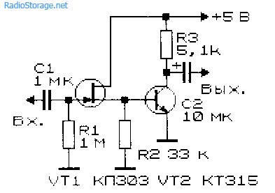
Economical ULF with three transistors
For portable electronic equipment important parameter is the efficiency of ULF. The diagram of such a ULF is shown in Fig. 10 [RL 3/00-14]. Here, a cascade connection of field-effect transistor VT1 and bipolar transistor VT3, and transistor VT2 is turned on in such a way that it stabilizes the operating point of VT1 and VT3.
As the input voltage increases, this transistor shunts the emitter-base junction of VT3 and reduces the value of the current flowing through transistors VT1 and VT3.

Rice. 10. Simple scheme economical amplifier LF on three transistors.
As in the above circuit (see Fig. 6), the input resistance of this ULF can be set in the range from tens of ohms to tens of megohms. A telephone capsule, for example, TK-67 or TM-2V, was used as a load. The telephone capsule, connected using a plug, can simultaneously serve as a power switch for the circuit.
The ULF supply voltage ranges from 1.5 to 15 V, although the functionality of the device is maintained even when the supply voltage is reduced to 0.6 V. In the supply voltage range of 2... 15 V, the current consumed by the amplifier is described by the expression:
1(μA) = 52 + 13*(Upit)*(Upit),
where Upit is the supply voltage in Volts (V).
If you turn off transistor VT2, the current consumed by the device increases by an order of magnitude.
Two-stage ULF with direct coupling between stages
Examples of ULFs with direct connections and minimal selection of operating modes are the circuits shown in Fig. 11 - 14. They have high gain and good stability.

Rice. 11. Simple two-stage ULF for a microphone (low noise level, high gain).

Rice. 12. Two-stage low-frequency amplifier using KT315 transistors.

Rice. 13. Two-stage low-frequency amplifier using KT315 transistors - option 2.
The microphone amplifier (Fig. 11) is characterized by a low level of self-noise and a high gain [MK 5/83-XIV]. An electrodynamic type microphone was used as the VM1 microphone.
A telephone capsule can also act as a microphone. Stabilization of the operating point (initial bias at the base of the input transistor) of the amplifiers in Fig. 11 - 13 is carried out due to the voltage drop across the emitter resistance of the second amplification stage.
Rice. 14. Two-stage ULF with field-effect transistor.
The amplifier (Fig. 14), which has a high input resistance (about 1 MOhm), is made on a field-effect transistor VT1 (source follower) and a bipolar transistor - VT2 (with a common one).
Cascade low frequency amplifier field effect transistors, which also has a high input impedance, is shown in Fig. 15.

Rice. 15. circuit of a simple two-stage ULF using two field-effect transistors.
ULF circuits for working with low-Ohm loads
Typical ULFs, designed to operate with low-impedance loads and having an output power of tens of mW and higher, are shown in Fig. 16, 17.

Rice. 16. A simple ULF for working with a low-resistance load.
Electrodynamic head BA1 can be connected to the output of the amplifier, as shown in Fig. 16, or diagonally to the bridge (Fig. 17). If the power source is made of two series-connected batteries (accumulators), the right output of the head BA1 according to the diagram can be connected to their midpoint directly, without capacitors SZ, C4.

Rice. 17. Circuit of a low-frequency amplifier with the inclusion of a low-resistance load in the diagonal of the bridge.
If you need a circuit for a simple tube ULF, then such an amplifier can be assembled even using one tube, look at our electronics website in the corresponding section.
Literature: Shustov M.A. Practical circuit design (Book 1), 2003.
Corrections in the publication: in Fig. 16 and 17, instead of diode D9, a chain of diodes is installed.
Most audio lovers are quite categorical and are not ready to compromise when choosing equipment, rightly believing that the perceived sound must be clear, strong and impressive. How to achieve this?
Search data for your request:
Preamplifier on KT315
Schemes, reference books, datasheets:
Price lists, prices:
Discussions, articles, manuals:
Wait for the search to complete in all databases.
Upon completion, a link will appear to access the found materials.
Perhaps the main role in resolving this issue will be played by the choice of amplifier.
Function
The amplifier is responsible for the quality and power of sound reproduction. At the same time, when purchasing, you should pay attention to the following designations, which mark the introduction of high technologies in the production of audio equipment:
- Hi-fi. Provides maximum purity and accuracy of sound, freeing it from extraneous noise and distortion.
- Hi-end. The choice of a perfectionist who is willing to pay a lot for the pleasure of discerning the smallest nuances of his favorite musical compositions. Hand-assembled equipment is often included in this category.
Specifications you should pay attention to:
- Entrance and output power. The rated output power is of decisive importance, because edge values are often unreliable.
- Frequency range. Varies from 20 to 20000 Hz.
- Nonlinear distortion factor. Everything is simple here - the less the better. The ideal value, according to experts, is 0.1%.
- Signal to noise ratio. Modern technology assumes a value of this indicator over 100 dB, which minimizes extraneous noise when listening.
- Dumping factor. Reflects the output impedance of the amplifier in its relation to the nominal load impedance. In other words, a sufficient damping factor (more than 100) reduces the occurrence of unnecessary vibrations of equipment, etc.
Something to remember: making quality amplifiers- a labor-intensive and high-tech process, respectively, too low price at decent characteristics should alert you.
Classification
To understand the variety of market offers, it is necessary to distinguish the product according to various criteria. Amplifiers can be classified:
- By power. Preliminary is a kind of intermediate link between the sound source and the final power amplifier. The power amplifier, in turn, is responsible for the strength and volume of the output signal. Together they form a complete amplifier.
Important: the primary conversion and signal processing takes place in the preamplifiers.
- Based on the element base, there are tube, transistor and integrated minds. The latter arose with the goal of combining the advantages and minimizing the disadvantages of the first two, for example, the sound quality of tube amplifiers and the compactness of transistor amplifiers.
- Based on their operating mode, amplifiers are divided into classes. The main classes are A, B, AB. If Class A amplifiers use a lot of power, but produce high-quality sound, Class B amplifiers are exactly the opposite, Class AB seems to be the optimal choice, representing a compromise between signal quality and fairly high efficiency. There are also classes C, D, H and G, which arose with the use of digital technologies. There are also single-cycle and push-pull operating modes of the output stage.
- Depending on the number of channels, amplifiers can be single-, double- and multi-channel. The latter are actively used in home theaters to create volumetric and realistic sound. Most often there are two-channel ones for right and left audio systems, respectively.
Attention: studying the technical components of the purchase is, of course, necessary, but often the decisive factor is simply listening to the equipment according to the principle of whether it sounds or not.
Application
The choice of amplifier is largely justified by the purposes for which it is purchased. We list the main areas of use of audio amplifiers:
- As part of a home audio system. It's obvious that best choice is a tube two-channel single-ended class A, also optimal choice can form a three-channel class AB, where one channel is designated for a subwoofer, with a Hi-fi function.
- For car audio system. The most popular are four-channel AB or D class amplifiers, depending on the financial capabilities of the buyer. Cars also require a crossover function for smooth frequency control, allowing frequencies in the high or low range to be cut as needed.
- In concert equipment. The quality and capabilities of professional equipment are justifiably more demanding. high requirements due to the large distribution space sound signals, as well as a high need for intensity and duration of use. Thus, it is recommended to purchase an amplifier of at least class D, capable of operating almost at the limit of its power (70-80% of the declared one), preferably in a housing made of high-tech materials that protects from negative weather conditions and mechanical influences.
- In studio equipment. All of the above is also true for studio equipment. We can add about the largest frequency reproduction range - from 10 Hz to 100 kHz in comparison with that from 20 Hz to 20 kHz in a household amplifier. Also noteworthy is the ability to separately adjust the volume on different channels.
Thus, in order to enjoy clear and high-quality sound for a long time, it is advisable to study in advance all the variety of offers and select the audio equipment option that best suits your needs.
- 03.10.2014
The figure shows the power supply circuit for a GSM/GPRS module based on the TPS54260 chip, developed by Texas Instruments. The nominal input voltage in this circuit is 12 V, and the full operating range is 8 ... 40 V. The calculation methodology and test results are described in detail in the document “Creating GSM /GPRS Power Supply from TPS54260”. In the same document you can find a diagram for the rated voltage...
- 04.10.2014
There are quite a lot of power regulator circuits based on thyristors or triacs, where adjustment is carried out by changing the unlocking angle. Regulators with such a circuit create interference in the network, so they can only be used with bulky LC filters. In cases where it is not important that power is supplied to the load every half-cycle, but what matters is...
- 28.09.2014
The schematic diagram of such a player is shown in the figure. The amplifier is designed to operate on 4 speakers (2 front and 2 rear). The rear speakers are two-way, each consisting of one elliptical speaker of a fairly large diameter and one tweeter. The front channels are simpler - each consists of one full-range speaker. Rear channels have a rise in frequency response at frequencies above...
- 25.09.2014
The development of nuclear energy and the widespread use of sources of ionizing radiation in various fields of science and technology, as well as their possible appearance in everyday conditions, require familiarization with the properties and methods of recording alpha, beta and gamma radiation, as well as the acquisition of relevant knowledge and practical skills in protection from their influence. Assessing and conducting research...
- 21.09.2014
A time relay with a power of no more than 100 W with a delay time of about 10 minutes for turning off the lighting lamp can be assembled using schematic diagram shown in the figure. The device contains a rectifier bridge VD1-VD4, a thyristor VS1, a control transistor VT1 and a timing unit on capacitor C1, zener diode VD2 and transistor VT2. When closing the contacts of switch SA1 ...
An acquaintance called me one evening and said: “Ed! I need a larger headphone amplifier Sven”
He bought headphones for 50 UAH, but the output on the computer is very weak for them. After thinking, I saw that there were no microcircuits, I went to rummage through the archives and look, somewhere I had a circuit with KT315 transistors. I don’t remember where it came from, but I remember that the scheme works. I put it together and this is what I got
Here is a diagram of this device:

I used the following parts for the harness:
C1 = 1mF 6V
C2 = 470mF 16V
C3 = 3300mF 16V
R1 = 1k
R2 = 51k
R3 = 100k
R4 = 100k
R5 = 1k
R6 = 3k
The device does not require configuration. The quiescent current is 25mA, the voltage between the output transistors is 2.4V. The amplifier is powered by a 9 volt battery
The scheme is simple and universal, any beginner can repeat it
I assembled all this on a breadboard. There is no longer an opportunity to take a photo, my friend accidentally dropped this device into a well along with headphones, I don’t want to make a new amplifier, I’m working on another project right now.
From memory the amp worked well. The sound is soft and pleasant. The battery lasted for 15 hours.

Printed circuit board of a simple amplifier on KT315 (View from the tracks)
Related Posts
I took the 3GDSH-1 speakers out of the TVs so that they wouldn’t lie idle and decided to make speakers, but since I have an external amplifier with a subwoofer, that means I’ll be assembling satellites.
Hello everyone, dear radio amateurs and audiophiles! Today I will tell you how to modify the high-frequency speaker 3GD-31 (-1300) also known as 5GDV-1. They were used in such speaker systems, like 10MAS-1 and 1M, 15MAS, 25AS-109…….
Hello dear readers. Yes, it’s been a while since I wrote a blog post, but with all responsibility I want to say that now I will try to keep up and will write reviews and articles…….
Hello dear visitor. I know why you are reading this article. Yes, yes I know. No what are you? I'm not a telepath, I just know why you ended up on this page. Surely......
And again, my friend Vyacheslav (SAXON_1996) wants to share his work on speakers. Word to Vyacheslav I somehow got one 10MAC speaker with a filter and a high-frequency speaker. I haven’t…… for a long time.
Figure 1 shows the circuit of the inverting amplifier direct current, the transistor is connected according to a common emitter circuit:
Figure 1 - Circuit of the DC amplifier on the KT315B.
Let's consider the calculation of circuit elements. Let's say the circuit is powered from a source with a voltage of 5V (this could be, for example network adapter), we select the collector current Ik of transistor VT1 so that it does not exceed the maximum permissible current for the selected transistor (for KT315B the maximum collector current Ikmax = 100 mA). Let's choose Ik=5mA. To calculate the resistance of the resistor Rk, divide the supply voltage Up by the collector current:
If the resistance does not fall into the standard series of resistances, then you need to select the closest value and recalculate the collector current.
()
Using the family of output current-voltage characteristics, we will construct a load line along the points Up and Ik (shown in red). On the load line, select the operating point (shown in blue) in the middle.
Figure 2 - Output current-voltage characteristics, load line and operating point
In Figure 2, the operating point does not fall on any of the available characteristics but is slightly below the characteristic for the base current Ib = 0.05 mA, so we will choose the base current a little less, for example Ib = 0.03 mA. Using the selected base current Ib and the input characteristic for a temperature of 25°C and voltage Uke = 0, we find the voltage Ube:
Figure 3 - Input characteristics of the transistor for selecting voltage Ube
For the base current Ib = 0.03 mA, we will find the voltage Ube but choose a little more since Uke>0 and the characteristic will be located to the right, for example, choose Ube = 0.8V. Next, we select the resistor current Rd1, this current should be greater than the base current but not so large that most of the power is lost in it, we select this current three times greater than the base current:
Using Kirchhoff's first law, we find the resistor current Rd2:
Let us designate the found currents and voltages in the diagram:
Figure 4 - Amplifier circuit with found branch currents and node voltages
Let's calculate the resistance of resistor Rd1 and select its closest value from the standard series of resistances:
Let's calculate the resistance of the resistor Rd2 and select its closest value from the standard series of resistances:
Let's designate the resistor resistances in the diagram:
Figure 5 - DC amplifier on KT315B.
Since the calculation is approximate, it may be necessary to select elements after assembling the circuit and checking the output voltage, elements Rd1 and/or Rd2 in this case must be selected so that the output voltage is close to the selected voltage Ube.
To amplify the alternating current, capacitors must be placed at the input and output to pass only the variable component of the amplified signal, since the constant component changes the operating mode of the transistor. The capacitors at the input and output should not create much resistance for the flow of alternating current. For thermal stabilization, you can place a resistor with a small resistance in the emitter circuit and a capacitor in parallel with it to weaken the feedback alternating current. The resistor in the emitter circuit, along with the divider resistors, will set the operating mode of the transistor.
The photo below shows an amplifier assembled according to the circuit in Figure 2:
There is no voltage applied to the amplifier input; a voltmeter connected to the output shows 2.6V, which is close to the selected value. If you apply a voltage of normal polarity to the input (such as in Figure 5), then the output voltage will decrease (the amplifier inverts the signal):

If you apply a voltage of reverse polarity to the input, the output voltage will increase but not more than the supply voltage:

The decrease in voltage at the input, when connected to the input of a source, is less than the increase in voltage at the output, which indicates that the input signal is being amplified with inversion. The common-emitter circuit produces greater power amplification than the common-base-common-emitter circuit, but unlike the other two, it produces signal inversion. If it is necessary to amplify DC power without inversion, then you can cascade connect two circuits in Figure 5, but it is necessary to take into account that the first stage will change the operating mode of the transistor of the second stage, so the resistance of the resistors in the second stage will need to be selected so that this change is as possible less. Also, with a cascade connection, the gain of the entire amplifier will increase (it will be equal to the product of the gain of the first stage and the gain of the second).
