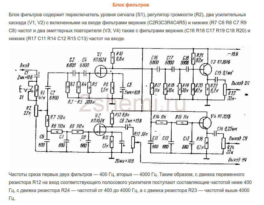
Preamplifier with tone on chip. Powerful and high-quality homemade sound amplifier. Active volume control
Recently, a certain person asked me to build him an amplifier of sufficient power and separate amplification channels for low, medium and high frequencies. Before this I had already collected it more than once for myself as an experiment and, I must say, the experiments were very successful. The sound quality is even inexpensive speakers the not very high level is noticeably improved compared, for example, with the option of using passive filters in the speakers themselves. In addition, it becomes possible to quite easily change the crossover frequencies and the gain of each individual band and, thus, it is easier to achieve a uniform frequency response of the entire sound amplification path. The amplifier used ready-made circuits that had previously been tested more than once in simpler designs.
Structural scheme
The figure below shows the circuit diagram of channel 1:

As can be seen from the diagram, the amplifier has three inputs, one of which provides simple opportunity adding a preamplifier-corrector for a vinyl player (if necessary), an input switch, a preamplifier-tone control (also three-band, with adjustable HF/MF/LF levels), a volume control, a filter block for three bands with adjustable gain levels for each band with the ability disabling filtering and a power supply for high-power final amplifiers (unstabilized) and a stabilizer for the “low-current” part (preliminary amplification stages).
Pre-amplifier-timbre block
A diagram was used as it, which had been tested more than once before, which, despite its simplicity and availability of details, shows quite good characteristics. The diagram (like all subsequent ones) was once published in the magazine “Radio” and then published more than once on various sites on the Internet:
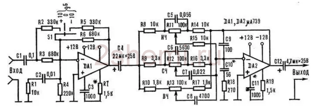
The input stage on DA1 contains a gain level switch (-10; 0; +10 dB), which simplifies the matching of the entire amplifier with signal sources of different levels, and the tone control is directly assembled on DA2. The circuit is not capricious to some variation in the values of the elements and does not require any adjustment. As an op-amp, you can use any microcircuits used in the audio paths of amplifiers, for example, here (and in subsequent circuits) I tried the imported BA4558, TL072 and LM2904. Any will do, but it is better, of course, to choose op-amp options with the lowest possible noise level and high performance (input voltage slew factor). These parameters can be viewed in reference books (datasheets). Of course, it is not at all necessary to use this particular scheme here; it is quite possible, for example, to make not a three-band, but a regular (standard) two-band tone block. But not a “passive” circuit, but with amplification-matching stages at the input and output on transistors or an op-amp.
Filter block
If you wish, you can also find a lot of filter circuits, since there are now enough publications on the topic of multi-band amplifiers. To make this task easier and just as an example, I will list here a few possible schemes found in various sources:
- the circuit that I used in this amplifier, since the crossover frequencies turned out to be exactly what the “customer” needed - 500 Hz and 5 kHz and I didn’t have to recalculate anything.

- the second circuit, simpler on an op-amp.
And another one possible scheme, on transistors:
As yours already wrote, I chose the first scheme because of the fairly high-quality filtering of the bands and the correspondence of the band separation frequencies to the specified ones. Only at the outputs of each channel (band) simple gain level controls were added (as was done, for example, in the third circuit, using transistors). Regulators can be supplied from 30 to 100 kOhm. Operational amplifiers and transistors in all circuits can be replaced with modern imported ones (taking into account the pinout!) to obtain best parameters schemes All these circuits do not require any adjustment unless you need to change the crossover frequencies. Unfortunately, I am not able to provide information on the recalculation of these interface frequencies, since the circuits were looked for as “ready-made” examples and detailed descriptions was not included with them.
The ability to disable filtering on the MF and HF channels has been added to the filter block circuit (the first of three circuits). For this purpose, two push-button switches of the P2K type were installed, with the help of which you can simply close the connection points of the filter inputs - R10C9 with their corresponding outputs - “HF output” and “MF output”. In this case, through these channels there is a full sound signal.
Power amplifiers
From the output of each filter channel, HF-MF-LF signals are fed to the inputs of power amplifiers, which can also be assembled using any of the known circuits, depending on the required power of the entire amplifier. I made the UMZCH according to the long-known scheme from the magazine “Radio”, No. 3, 1991, p. 51. Here I provide a link to the “original source”, since there are many opinions and disputes regarding this scheme regarding its “quality”. The fact is that at first glance this is a class “B” amplifier circuit with the inevitable presence of “step” distortion, but this is not so. The circuit uses current control of the transistors of the output stage, which allows you to get rid of these shortcomings during normal, standard switching on. At the same time, the circuit is very simple, is not critical to the parts used, and even the transistors do not require special preliminary selection of parameters. In addition, the circuit is convenient in that powerful output transistors can be placed on one heat sink in pairs without insulating spacers, since the collector terminals are connected at the point " output”, which greatly simplifies the installation of the amplifier:

When setting up, it is only IMPORTANT to select the correct operating modes of the transistors of the pre-final stage (by selecting resistors R7R8) - at the bases of these transistors in the “rest” mode and without load at the output (dynamics) there should be a voltage in the range of 0.4-0.6 volts. The supply voltage for such amplifiers (there should be 6 of them, respectively) was raised to 32 volts with the replacement of the output transistors with 2SA1943 and 2SC5200, the resistance of the R10R12 resistors should also be increased to 1.5 kOhm (to “make life easier” for the zener diodes in the circuit power supply of input op-amps). The op-amps were also replaced with BA4558, in which case the “zero setting” circuit (outputs 2 and 6 in the diagram) is no longer needed and, accordingly, the pinout changes when soldering the microcircuit. As a result, when tested, each amplifier using this circuit produced power up to 150 watts (short-term) with a completely adequate degree of heating of the radiator.
ULF power supply
Two transformers with blocks of rectifiers and filters were used as a power supply according to the usual, standard scheme. To power the low-frequency band channels (left and right channels) - a 250-watt transformer, a rectifier based on diode assemblies such as MBR2560 or similar, and 40,000 uF x 50 volt capacitors in each power arm. For the midrange and high-frequency channels - a 350-watt transformer (taken from a burnt-out Yamaha receiver), a rectifier - a TS6P06G diode assembly and a filter - two capacitors of 25,000 uF x 63 volts for each power arm. All electrolytic filter capacitors are shunted by film capacitors with a capacity of 1 microfarad x 63 volts.
In general, the power supply can have one transformer, of course, but with its corresponding power. The power of the amplifier as a whole in this case is determined solely by the capabilities of the power source. All preamplifiers (timbre block, filters) are also powered from one of these transformers (possibly from any of them), but through an additional bipolar stabilizer unit assembled on a KREN type MS (or imported) or via any of standard schemes on transistors.
Homemade amplifier design
This was, perhaps, the most difficult moment in manufacturing, since there was no suitable ready-made housing and I had to come up with possible options :-)) In order not to sculpt a bunch of separate radiators, I decided to use a radiator housing from a car 4-channel amplifier, quite large in size, something like this:

All the “internals” were, naturally, removed and the layout turned out something like this (unfortunately, I didn’t take a corresponding photo):

— as you can see, six terminal UMZCH boards and a pre-amplifier-timbre block board were installed in this radiator cover. The filter block board no longer fit, so it was secured to a structure made from an aluminum corner that was then added (it can be seen in the pictures). Also, transformers, rectifiers and power supply filters were installed in this “frame”.
The view (from the front) with all the switches and controls turned out like this:

Rear view, with speaker output terminals and fuse box (since no circuits electronic protection were not made due to lack of space in the design and in order not to complicate the design):

Subsequently, the frame from the corner is, of course, supposed to be covered with decorative panels to give the product a more “marketable” appearance, but this will be done by the “customer” himself, according to his personal taste. But in general, in terms of sound quality and power, the design turned out to be quite decent. Author of the material: Andrey Baryshev (especially for the site website).
This stereo preamplifier is based on the popular operational amplifier NE5532 and several discrete elements. The preamplifier is suitable for working with any signal source, such as an MP3 player or computer, and in addition to the final power amplifier it will allow you to get good sound at home.
The preamplifier has a tone block that allows you to adjust the low and high frequencies, as well as adjust the volume using three paired rotary potentiometers. Placing the potentiometers on the edge of the board eliminates the need for wires connecting the potentiometers to the board, which in turn improves the amplifier's noise performance.
The preamplifier is powered by a bipolar power supply with voltage ranging from +/-18 to +/-30 volts.
Operation of a pre-amplifier with a tone block
Schematic diagram preamp is shown in the figure below: 
The amplifier consists of two identical channels. Let's study the operation of a preamplifier using one of them. The input signal is fed to GP1 and goes directly to a high pass filter consisting of capacitor C1 (1uF) and resistor R1 (100k) with a cutoff frequency of about 1.5Hz, this effectively cuts off the DC component and the lowest frequencies.
Next, the signal goes to the non-inverting amplifier U1 (NE5532) and resistors R3 (10k) and R7 (4.7 k), which provides a signal amplification of 1.5 times. A small capacitor C3 (10 pF) prevents excitation, while C5 (1 µF) separates the circuits on amplifiers U1 and U2 (NE5532).
The frequency regulator is built on amplifier U2, and the frequency control itself is built in the classic way. Elements that change the characteristics are located in the negative feedback loop of amplifier U2. When both controls are in the center position, resistance X1 (derived from elements: R9 (10k), C9 (33 nF), C7 (4.7 nF), and also: P1 (100k), P2 (100k), R11 (10k ) and R12 (3.3 k) - “in the middle position”) between the input signal and the inverting input of the amplifier U2 is equal to the resistance X2 (obtained from the elements: R15 (10 k), C11 (33 nF), C13 (4.7 nF) and in the middle also: P1, P2, R11 and R12 - “in the middle position”) between the output of amplifier U2 and the inverting input. The gain A is expressed by the following dependence:
It is equal to 1 for the entire operating frequency range of the amplifier.
P1 is responsible for regulation low frequencies. For high frequencies, capacitors C9 and C11 are short-circuited, so adjustment with the potentiometer has no effect at these frequencies. The potentiometer is responsible for adjusting the high frequencies, and due to the exclusion of capacitors C7 and C13, the adjustment has no effect on the low frequencies.
The signal from the output of the frequency regulator goes through resistor R17 (4.7 k) to the volume control potentiometer P3 (100k) and then to the next amplification circuit, namely U5 (NE5532). Elements R19 (15k) and R21 (33k) configure U5 to work as an inverting amplifier with a gain of about 2. From the output of U5, the signal through the filter R23 (100P), C21 (1 uF) and R25 (100k) goes to the output of the preamplifier GP3 .
The supply voltage for the operational amplifiers is obtained using regulators U3 (78L15) and U4 (79L15), and is filtered using capacitors C15–C16 and C17–C18. In addition, the power supply to each of the four op-amps is smoothed using capacitors C19-C20 and C23-C26 (100 nF).
(unknown, downloads: 4,037)
Pre-amplifier circuit with tone control.
Greetings, friends. Below in the article, a pre-amplifier project from Maxim Vasiliev is presented, which is essentially a remake of Sukhov’s preamplifier by transferring the circuit from the 157 series of microcircuits to import. More detailed information You can find it on KOTA and the vegalab forum by searching for “Vasiliev’s Complete Amplifier”. Schematic diagram:
To enlarge the image, click on the picture.

The circuit uses dual operational amplifiers. For example, you can put OPA2134P, TL072 or NE5532, as you like or whichever of these on this moment is at hand. The following figure shows the pinout layout of the microcircuits; the above ones are the same, so no matter which MS you use, you don’t need to make any changes to the board:

We won’t write about which microcircuits sound better; you can find a lot of information about this on amateur radio forums, and there are plenty of them on the Internet.
The power supply is bipolar +/- 12…15 Volts.
Variable resistors of group “A” (imported) are used as volume, balance and tone controls; if you use domestic variables, choose with group “B”
The printed circuit board is made of double-sided fiberglass. The top layer is not etched; it is used as a screen. Board dimensions 70x158 mm.
The appearance of the printed circuit board is shown in the following two figures:
A bipolar voltage stabilizer of 2 x 15 Volts on 78L15 and 79L15 chips has been added to the board. The figure below shows the pin layout of the 2N5551 transistor:

The circuit diagram and printed circuit board in LAY format can be downloaded via a direct link from our website. The archive file size for downloading is 0.53 Mb.
Don't dream, act!
Experiments with various preamps, volume and tone controls have shown that best quality sound is ensured with a minimum number of amplification stages, with passive regulators. In this case, adjustments at the input of the power amplifier are undesirable, since they lead to an increase in the level of nonlinear distortion of the complex. This effect was recently discovered by the famous audio equipment developer Douglas Self.
Thus, the following structure emerges for this part of the sound amplification path:
- passive bridge regulator of low and high frequencies,
- passive volume control,
- a pre-amplifier with a linear amplitude-frequency response (AFC) and minimal distortion in the operating frequency range.
The obvious drawback of adjustments at the preamplifier input is that the deterioration in the signal-to-noise ratio is largely offset by the high signal level modern devices sound reproduction.
Proposed preamplifier Can be used in high quality stereo amplifiers audio frequency. The tone control allows you to adjust the amplitude-frequency response (AFC) simultaneously on two channels in two frequency regions: lower and upper. As a result, the characteristics of the room and speaker systems, as well as the personal preferences of the listener.
And again a little history
The first contender for the role of a pre-amplifier with a tone control was D. Starodub’s circuit (Fig. 1). But the design never took root in a power amplifier: careful shielding and a power supply with an extremely low ripple level (about 50 μV) were required. However, the main reason was the lack of slider variable resistors.
Rice. 1. Diagram of a high-quality tone control block
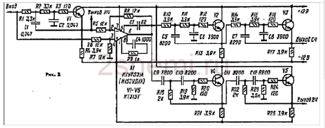
Through trial and error, I came up with a simple pre-amplifier circuit (Fig. 2), with which, however, the sound reproduction system far surpassed the sound of commercially produced equipment, according to at least, available to my friends and acquaintances.

Rice. 2. Schematic diagram of one pre-amplifier channel for UMZCH S. Batya and V. Sereda
The basis is taken from the circuit of the pre-amplifier of the stereophonic electrophone by Yu. Krasov and V. Cherkunov, demonstrated at the 26th All-Union Exhibition of Radio Amateur Designers. This is the left side of the circuit, including the tone controls.
The appearance of a cascade on transistors of different conductivities in the pre-amplifier (VT3, VT4) is associated with a discussion of amplifiers with the teacher of the television technology laboratory at the Department of Radio Systems A. S. Mirzoyants, with whom I worked as a student. During the work, linear cascades were needed for amplification TV signal, and Alexander Sergeevich reported that in his experience best characteristics have “topsy-turvy” structures, as he put it, that is, amplifiers on transistors of the opposite structure with direct communication. In the process of experimenting with UMZCH, I found out that this applies not only to television equipment, but also to sound reinforcement equipment. Subsequently, I often used similar schemes in my designs, including pairs field-effect transistor– bipolar transistor.
An attempt to use transistors of different structures in the first stage (composite emitter follower VT1, VT2) did not bring success, because with all the excellent characteristics (low noise level, low distortion), the circuit had a significant drawback - lower overload capacity compared to the emitter follower.
Pre-amplifier specifications:
Input resistance, kOhm= 300
Sensitivity, mV= 250
Depth of tone adjustments, dB:
at a frequency of 40 Hz=± 15
at 15 kHz=± 15
Depth of stereo balance adjustments, dB=± 6
Since new ideas arose during the design of amplifiers, I gave the old designs to someone, or sold them at a fixed rate of watt of output power / ruble. On one of my trips to Leningrad, I took this amplifier with me to sell it to a friend of a friend. Volodka said that this guy has a lot of Western equipment, and took the device to him for an audition. In the evening he told me the results: the young man turned on the amplifier, listened to a couple of things and was so satisfied with the sound that he paid the money without a word.
To be honest, when I found out that the comparison would take place with imported equipment, I didn’t particularly hope that the amplifier would make an impression. In addition, it was not fully completed - the top and side covers were missing.
Let's consider the circuit diagram of one pre-amplifier channel (Fig. 2). High-impedance volume (R2.1) and balance (R1.1) controls are installed at the input. From the middle terminal of resistor R2.1, through the transition capacitor C2, the sound signal is supplied to the composite emitter follower VT1, VT2, which is necessary for the normal operation of the passive tone control, made in a bridge circuit. In order to eliminate the attenuation introduced by the tone block and amplify the signal to the required level, a two-stage amplifier is installed on transistors VT3, VT4.
The preamplifier's power supply is unstabilized, from the positive arm of the power amplifier. The supply voltage is supplied to cascades VT3, VT4 through filter R17, C10, C13, and to the input emitter follower - R8, C4. The VD1 diode plays an important role: without it it was not possible to completely eliminate the background alternating current frequency 100 Hz at the output of the power amplifier.
Structurally, the pre-amplifier is made in a “line”, all parts are installed on printed circuit board, closed on top by a U-shaped screen made of steel 0.8 mm thick.
--
Thank you for your attention!
The calculation was performed using the following relationships: R1 = R3; R2 = 0.1R1; R4 = 0.01R1; R5 = 0.06R1; C1[nF] = 105/R3[Ohm]; C2 = 15C1; C3 = 22C1; C4 = 220C1.
With R1=R3=100 kOhm, the tone block will introduce attenuation of about 20 dB at a frequency of 1 kHz. You can take variable resistors R1 and R3 of a different value, even if, for definiteness, resistors with a resistance of 68 kOhm were available. It's easy to count the denominations fixed resistors and bridge tone control capacitors without referring to the program or table. 1: we reduce the resistance values of the resistors by 68/100=0.68 times and increase the capacitances of the capacitors by 1/0.68=1.47 times. We get R1=6.8 kOhm; R3=680 Ohm; R4=3.9 kOhm; C2=0.033 µF; C3=0.33 µF; C4=1500 pF; C5=0.022 µF.
For smooth tone control, variable resistors with an inverse logarithmic dependence (curve B) are required.
The program allows you to clearly view the operation of the designed tone control Tone Stack Calculator 1.3(Fig. 9).

Rice. 9. Modeling of tone controls for the circuit shown in Fig. 8
Program Tone Stack Calculator is designed to analyze seven typical circuits of passive tone controls and allows you to immediately show the frequency response when changing the position of the virtual controls.
Rice. 11. Schematic diagram of the tone block and pre-amplifier for the “student” UMZCH
An experimental test of several instances of operational amplifiers showed that even without a capacitor in the grounded branch of the negative feedback divider constant pressure the output is a few millivolts. However, for reasons of versatility of use, coupling capacitors (C1, C6) are included at the input of the tone control unit and the output of the pre-amplifier.
Depending on the required sensitivity of the amplifier, the resistance value of resistor R10 is selected from the table. 2. You should strive not for the exact value of the resistor resistances, but for their pairwise equality in the amplifier channels.
table 2 
▼ 🕗 02/25/12 ⚖️ 11.53 Kb ⇣ 149 Hello, reader! My name is Igor, I'm 45, I'm a Siberian and an avid amateur electronics engineer. I came up with, created and have been maintaining this wonderful site since 2006.
For more than 10 years, our magazine has existed only at my expense.
Good! The freebie is over. If you want files and useful articles, help me!
--
Thank you for your attention!
Igor Kotov, editor-in-chief of Datagor magazine
The main disadvantage of a passive tone control is the low gain. Another disadvantage is that to obtain a linear dependence of the volume level on the angle of rotation, it is necessary to use variable resistors with a logarithmic control characteristic (curve “B”).
The advantage of passive tone controls is less distortion than active ones (for example, the Baxandal tone control, Fig. 12).

Rice. 12. Active tone control by P. Baxandal
As can be seen from the diagram shown in Fig. 12, the active tone control contains passive elements (resistors R1 - R7, capacitors C1 - C4), connected to one hundred percent parallel negative feedback by voltage of operational amplifier DA1. The transmission coefficient of this regulator in the middle position of the tone control sliders R2 and R6 is equal to unity, and variable resistors with linear characteristic regulation (curve “A”). In other words, an active tone control is free from the disadvantages of a passive tone control.
However, in terms of sound quality, this regulator is clearly worse than a passive one, which even inexperienced listeners notice.
Rice. 13. Placement of parts on the printed circuit board
Elements related to the right channel of the preamplifier are indicated with a prime. The same marking is made in the printed circuit board file (with *.lay extension) - the inscription appears when the cursor is moved to the corresponding element.
First, small-sized parts are installed on the printed circuit board: wire jumpers, resistors, capacitors, ferrite “beads” and a socket for the microcircuit. Lastly, terminal blocks and variable resistors are installed.
After checking the installation, turn on the power and check the “zero” at the outputs of the operational amplifier. The offset is 2 – 4 mV.
If desired, you can drive the device from a sinusoidal generator and take the characteristics (Fig. 14).

Rice. 14. Installation for characterizing the preamplifier
--
Thank you for your attention!
Igor Kotov, editor-in-chief of Datagor magazine
Sources mentioned
1. Digest // Radiohobby, 2003, No. 3, pp. 10, 11.2. Starodub D. Block of tone controls for a high-quality bass amplifier // Radio, 1974, No. 5, p. 45, 46.
3. Shkritek P. Reference guide to audio circuitry. – M.: Mir, 1991, p. 150 – 153.
4. Shikhatov A. Passive tone controls // Radio, 1999, No. 1, p. 14, 15.
5. Rivkin L. Calculation of tone controls // Radio, 1969, No. 1, p. 40, 41.
6. Solntsev Yu. High-quality pre-amplifier // Radio, 1985, No. 4, pp. 32 – 35.
7. //www.moskatov.narod.ru/ (Program by E. Moskatov “Timbreblock 4.0.0.0”).
Vladimir Mosyagin (MVV)
Russia, Veliky Novgorod
I became interested in amateur radio from the fifth grade of high school.
Diploma specialty - radio engineer, Ph.D.
Author of the books “For a young radio amateur to read with a soldering iron”, “Secrets of amateur radio craftsmanship”, co-author of the series of books “To be read with a soldering iron” in the publishing house “SOLON-Press”, I have publications in the magazines “Radio”, “Instruments and Experimental Techniques”, etc. .
Reader vote

