How does a cellular communication circuit work? How does a cell phone work? Dual band and dual standard mobile phone
Mobile cellular
cellular- one of the types of mobile radio communications, which is based on cellular network . Key Feature lies in the fact that the total coverage area is divided into cells (cells), determined by the coverage areas of individual base stations (BS). The cells partially overlap and together form a network. On an ideal (flat and undeveloped) surface, the coverage area of one BS is a circle, so the network made up of them looks like a honeycomb with hexagonal cells (honeycombs).
It is noteworthy that in the English version the connection is called “cellular” or “cellular” (cellular), which does not take into account the hexagonal nature of the honeycomb.
The network consists of spatially separated transceivers operating in the same frequency range, and switching equipment that allows you to determine the current location of mobile subscribers and ensure continuity of communication when a subscriber moves from the coverage area of one transceiver to the coverage area of another.
Story
The first use of mobile telephone radio in the United States dates back to 1921: Detroit police used one-way dispatch communications in the 2 MHz band to transmit information from a central transmitter to vehicle-mounted receivers. In 1933, the NYPD began using a two-way mobile telephone radio system, also in the 2 MHz band. In 1934, the US Federal Communications Commission allocated 4 channels for telephone radio communications in the range of 30...40 MHz, and in 1940 about 10 thousand police vehicles were already using telephone radio communications. All of these systems used amplitude modulation. Frequency modulation began to be used in 1940 and by 1946 it had completely replaced amplitude modulation. The first public mobile radiotelephone appeared in 1946 (St. Louis, USA; Bell Telephone Laboratories), it used the 150 MHz band. In 1955, an 11-channel system began operating in the 150 MHz band, and in 1956, a 12-channel system in the 450 MHz band began operating. Both of these systems were simplex and used manual switching. Automatic duplex systems began operating in 1964 (150 MHz) and 1969 (450 MHz), respectively.
In the USSR In 1957, Moscow engineer L.I. Kupriyanovich created a prototype of a portable automatic duplex mobile radiotelephone LK-1 and a base station for it. The mobile radiotelephone weighed about three kilograms and had a range of 20-30 km. In 1958, Kupriyanovich created improved models of the device, weighing 0.5 kg and the size of a cigarette box. In the 60s, Hristo Bochvarov demonstrated his prototype of a pocket mobile radiotelephone in Bulgaria. At the Interorgtekhnika-66 exhibition, Bulgaria presents a kit for organizing local mobile communications from pocket mobile phones PAT-0.5 and ATRT-0.5 and base station RATC-10, providing connection for 10 subscribers.
At the end of the 50s, the development of the Altai car radiotelephone system began in the USSR, which was put into trial operation in 1963. The Altai system initially operated at a frequency of 150 MHz. In 1970, the Altai system operated in 30 cities of the USSR and the 330 MHz range was allocated for it.
In a similar way, with natural differences and on a smaller scale, the situation developed in other countries. Thus, in Norway, public telephone radio has been used for maritime mobile communications since 1931; in 1955 there were 27 coast radio stations in the country. Ground mobile connection began to develop after the Second World War in the form of private networks with manual switching. Thus, by 1970, mobile telephone radio communications, on the one hand, had already become quite widespread, but on the other, it clearly could not keep up with the rapidly growing needs, with a limited number of channels in strictly defined frequency bands. A solution was found in the form of a cellular communication system, which made it possible to dramatically increase capacity by reusing frequencies in a system with a cellular structure.
Of course, as usually happens in life, certain elements of the cellular communication system existed before. In particular, some semblance of a cellular system was used in 1949 in Detroit (USA) by a taxi dispatch service - with the reuse of frequencies in different cells when users manually switched channels at predetermined locations. However, the architecture of the system that is today known as the cellular communications system was outlined only in a technical report from the Bell System, submitted to the US Federal Communications Commission in December 1971. And from that time on, the development of cellular communications itself began, which became truly triumphant in 1985 g., in the last ten years or so.
In 1974, the US Federal Communications Commission decided to allocate a frequency band of 40 MHz in the 800 MHz band for cellular communications; in 1986 another 10 MHz was added in the same range. In 1978, tests of the first experimental cellular communication system for 2 thousand subscribers began in Chicago. Therefore, 1978 can be considered the year of the beginning practical application cellular communications. The first automated commercial cellular telephone system was also introduced in Chicago in October 1983 by American Telephone and Telegraph (AT&T). In Canada, cellular communications have been used since 1978, in Japan - since 1979, in the Scandinavian countries (Denmark, Norway, Sweden, Finland) - since 1981, in Spain and England - since 1982. As of July 1997 cellular communications operated in more than 140 countries on all continents, serving more than 150 million subscribers.
The first commercially successful cellular network was the Finnish Autoradiopuhelin (ARP) network. This name is translated into Russian as “Car radiotelephone”. Launched in the city, it reached 100% coverage of the territory of Finland in. The size of the cell was about 30 km, and there were more than 30 thousand subscribers in the city. It worked at a frequency of 150 MHz.
Operating principle of cellular communication
The main components of a cellular network are cell phones and base stations. Base stations are usually located on the roofs of buildings and towers. Being turned on cellular telephone listens to the airwaves, finding the signal from the base station. The phone then sends its unique identification code to the station. The telephone and the station maintain constant radio contact, periodically exchanging packets. Communication between the phone and the station can be via an analog protocol (NMT-450) or digital (DAMPS, GSM, English). handover).
Cellular networks can consist of base stations of different standards, which allows optimizing network operation and improving its coverage.
Cellular networks different operators connected to each other, as well as to the landline telephone network. This allows subscribers of one operator to make calls to subscribers of another operator, from mobile phones to landlines and from landlines to mobiles.
Operators in different countries can enter into roaming agreements. Thanks to such agreements, a subscriber, while abroad, can make and receive calls through the network of another operator (albeit at higher rates).
Cellular communications in Russia
In Russia, cellular communications began to be introduced in 1990, commercial use began on September 9, 1991, when the first cellular network in Russia was launched in St. Petersburg by Delta Telecom (operating in the NMT-450 standard) and the first symbolic cell phone call by the mayor of St. Petersburg Anatoly Sobchak. By July 1997, the total number of subscribers in Russia was about 300 thousand. As of 2007, the main cellular communication protocols used in Russia are GSM-900 and GSM-1800. In addition, UMTS also works. In particular, the first fragment of a network of this standard in Russia was put into operation on October 2, 2007 in St. Petersburg by MegaFon. In the Sverdlovsk region, the cellular communication network of the DAMPS standard continues to be used, company-owned Cellular Communications "MOTIV".
In Russia in December 2008, there were 187.8 million cellular users (based on the number of SIM cards sold). The penetration rate of cellular communications (the number of SIM cards per 100 inhabitants) on this date was thus 129.4%. In the regions, excluding Moscow, the penetration level exceeded 119.7%.
The market share of the largest mobile operators as of December 2008 was: 34.4% for MTS, 25.4% for VimpelCom and 23.0% for MegaFon.
In December 2007, the number of cellular users in Russia increased to 172.87 million subscribers, in Moscow - to 29.9, in St. Petersburg - to 9.7 million. Penetration level in Russia - up to 119.1%, Moscow - 176% , St. Petersburg - 153%. The market share of the largest cellular operators as of December 2007 was: MTS 30.9%, VimpelCom 29.2%, MegaFon 19.9%, other operators 20%.
According to data from the British research company Informa Telecoms & Media for 2006, the average cost of a minute of cellular communication for a consumer in Russia was $0.05 - this is the lowest among the G8 countries.
IDC based on research Russian market cellular communications concluded that in 2005, the total duration of calls on a cell phone by residents of the Russian Federation reached 155 billion minutes, and text messages 15 billion units were shipped.
According to a study by J"son & Partners, the number of SIM cards registered in Russia as of the end of November 2008 reached 183.8 million.
see also
Sources
Links
- Information site about generations and standards of cellular communications.
- Cellular communications in Russia 2002-2007, official statistics
| cellular in Russia | |
|---|---|
| Cellular operators | Utel Akos Altaisvyaz Baikalwestcom Beeline ETK MegaFon Motive MTS NSS NTK SMARTS Sky Link Sonet Sotel SSB STEC GSM TomskTeleCom UUSS Digital expansion |
| Cell phone sales networks | Divizion Symphony AltTelecom Banzai Betalink Euroset ION Svyaznoy Spectrum Communication Telephone.Ru Teleforum Tochka Ultra Digital City Eldorado |
| Cellular standards | D-AMPS GSM IMT-MC-450 IS-95 |
How cellular communication works
The basic principles of cellular telephony are quite simple. The Federal Communications Commission originally established geographic coverage areas for cellular radio systems based on modified 1980 Census data. The idea behind cellular communications is that each area is subdivided into hexagonal-shaped cells that fit together to form a honeycomb-like structure, as shown in the figure. 6.1, a. The hexagonal shape was chosen because it provides the most efficient transmission, approximately matching the circular radiation pattern while eliminating the gaps that always appear between adjacent circles.
A cell is defined by its physical size, population, and traffic patterns. The Federal Communications Commission does not regulate the number of cells in a system or their size, leaving operators to set these parameters in accordance with expected traffic patterns. Each geographic area is allocated a fixed number of cellular voice channels. Physical Dimensions Cells depend on subscriber density and call structure. For example, large cells (macrocells) typically have a radius of 1.6 to 24 km with a base station transmitter power of 1 W to 6 W. The smallest cells (microcells) typically have a radius of 460 m or less with a base station transmitter power of 0.1 W to 1 W. Figure 6.1b shows a cellular configuration with two cell sizes.

Figure 6.1. – Honeycomb structure of cells a); honeycomb structure with honeycombs of two sizes b) classification of honeycombs c)
Microcells are most often used in regions with high density population. Due to their short range, microcells are less susceptible to interference that degrades transmission quality, such as reflections and signal delays.
A macro cell can be superimposed on a group of micro cells, with the micro cells serving slow moving mobile devices and the macro cell serving fast moving mobile devices. The mobile device is able to determine the speed of its movement as fast or slow. This allows you to reduce the number of transitions from one cell to another and the correction of location data.
The algorithm for moving from one cell to another can be changed at short distances between the mobile device and the microcell base station.
Sometimes the radio signals in a cell are too weak to provide reliable communications indoors. This is especially true for well-shielded areas and areas with high levels of interference. In such cases, very small cells are used - picocells. Indoor picocells can use the same frequencies as regular cells of this region, especially in favorable environments, such as underground tunnels.
When planning systems using hexagonal-shaped cells, base station transmitters can be located in the center of the cell, on the edge of the cell, or at the top of the cell (Figure 6.2 a, b, c, respectively). Cells with a transmitter in the center typically use omnidirectional antennas, while cells with transmitters on an edge or vertex typically use sectorial directional antennas.
 Omnidirectional antennas radiate and receive signals equally in all directions.
Figure 6.2 – Placement of transmitters in cells: in the center a); on edge b); at the top c)
In a cellular communication system, one powerful fixed base station located high above the city center can be replaced by numerous identical low-power stations that are installed in the coverage area at sites located closer to the ground.
Cells using the same group of radio channels can avoid interference if they are properly spaced. In this case, frequency reuse is observed. Frequency reuse is the allocation of the same group of frequencies (channels) to several cells, provided that these cells are separated by significant distances. Frequency reuse is facilitated by reducing the coverage area of each cell. The base station of each cell is allocated a group of operating frequencies that differ from the frequencies of neighboring cells, and the base station antennas are selected in such a way as to cover the desired service area within its cell. Since the service area is limited to the boundaries of a single cell, different cells can use the same group of operating frequencies without interference, provided that two such cells are located at a sufficient distance from each other.
The geographic service area of a cellular system containing several groups of cells is divided into clusters (Figure 6.3). Each cluster consists of seven cells, which are allocated the same number of full-duplex communication channels. Cells with the same letter designations use the same group of operating frequencies. As can be seen from the figure, the same frequency groups are used in all three clusters, which makes it possible to triple the number available channels mobile communications. Letters A, B, C, D, E, F And G represent seven frequency groups.
 |
Figure 6.3 – Principle of frequency reuse in cellular communications
Consider a system with a fixed number of full-duplex channels available in some area. Each service area is divided into clusters and receives a group of channels that are distributed between N honeycombs of the cluster, grouping into non-repeating combinations. All cells have the same number of channels, but they can serve single-sized areas.
Thus, the total number of cellular channels available in the cluster can be represented by the expression:
F=GN (6.1)
Where F– the number of full-duplex cellular communication channels available in the cluster;
G– number of channels in a cell;
N– number of cells in the cluster.
If the cluster is "copied" within a given service area m times, then the total number of full duplex channels will be:
C = mGN = mF (6.2)
Where WITH– total number of channels in a given zone;
m– number of clusters in a given zone.
From expressions (6.1) and (6.2) it is clear that the total number of channels in a cellular telephone system is directly proportional to the number of “repetitions” of a cluster in a given service area. If the cluster size is reduced while the cell size remains the same, more clusters will be needed to cover a given service area and the total number of channels in the system will increase.
The number of subscribers who can simultaneously use the same group of frequencies (channels), while not being in neighboring cells of a small service area (for example, within a city), depends on the total number of cells in a given area. Typically the number of such subscribers is four, but in densely populated regions it can be much higher. This number is called frequency reuse factor or FRF – Frequency reuse factor. Mathematically it can be expressed by the relation:
| (6.3) |
Where N– the total number of full-duplex channels in the service area;
WITH– the total number of full-duplex channels in the cell.
With the projected increase in cellular traffic, the increased demand for service is met by reducing the size of the cell, dividing it into several cells, each with its own base station. Effective cell separation allows the system to handle more calls as long as the cells are not too small. If the cell diameter becomes less than 460 m, then the base stations of neighboring cells will influence each other. The relationship between frequency reuse and cluster size determines how scale cellular system in case of increasing subscriber density. The fewer cells in a cluster, the greater the likelihood of mutual influences between channels.
![]() Because cells are hexagonal in shape, each cell always has six equally spaced adjacent cells, and the angles between the lines connecting the center of any cell to the centers of neighboring cells are multiples of 60°. Therefore, the number of possible cluster sizes and cell layouts is limited. To connect cells to each other without gaps (in a mosaic way), the geometric dimensions of the hexagon must be such that the number of cells in the cluster satisfies the condition:
Because cells are hexagonal in shape, each cell always has six equally spaced adjacent cells, and the angles between the lines connecting the center of any cell to the centers of neighboring cells are multiples of 60°. Therefore, the number of possible cluster sizes and cell layouts is limited. To connect cells to each other without gaps (in a mosaic way), the geometric dimensions of the hexagon must be such that the number of cells in the cluster satisfies the condition:
| (6.4) |
Where N– number of cells in the cluster; i And j– non-negative integers.
Finding a route to the nearest cells with a shared channel (the so-called first-tier cells) occurs as follows:
Move to i cells (through the centers of neighboring cells):
Move to j cells forward (through the centers of neighboring cells).
For example, the number of cells in the cluster and the location of the first tier cells for the following values: j = 2. i = 3 will be determined from expression 6.4 (Figure 6.4) N = 3 2 + 3 2 + 2 2 = 19.
Figure 6.5 shows the six closest cells using the same channels as the cell A.
The process of handing over from one cell to another, i.e. when a mobile device moves from base station 1 to base station 2 (Figure 6.6) includes four main stages:
1) initiation - the mobile device or network detects the need for handover and initiates the necessary network procedures;
2) resource reservation - using appropriate network procedures, network resources necessary for service transfer (voice channel and control channel) are reserved;
3) execution – direct transfer of control from one base station to another;
4) termination - excess network resources are released, becoming available to other mobile devices.

Figure 6.6 – Handover
Communication between mobile phones, or cellular phones as they are also called, is carried out not using wires, as in a conventional telephone system, but through radio waves. To call a mobile phone, you need to dial the number as usual. Thus, the radio message arrives at a base station controlled by the cellular telephone company.
At a station that services all calls within a given radius or zone, the controller device detects a call on an open radio channel. In addition, it sends a signal to the automatic telephone exchange of the cellular network. Reading special codes, transmitted by telephone,
The automatic telephone exchange monitors the movement of the vehicle in the area of the first station. If during a call the car passes a zone and ends up in the next one, the call is automatically transferred to the base station operating in that zone. When making a call on a mobile phone, the caller connects to an automatic cellular telephone exchange, which locates the mobile phone, requests an open radio channel from the circuit controller and communicates - through the base station - with the desired number. Then mobile phone calls. When the driver picks up the phone, the circuit is completed.
Base station operation
Each base station receives signals emitted within a three to six mile radius. To avoid noise, base stations with coinciding boundaries must operate on different frequency channels. But even within the same city, stations quite distant from each other can easily operate on the same channel.
The local telephone system, which serves both homes and businesses, is based on wires running underground and above ground and connected to an automatic exchange.
Location and channel
The automatic telephone exchange detects the location of the moving vehicle while the circuit controller routes the call to the communication channel.
Call area
When the vehicle moves outside the range of the most distant base station, the driver can no longer use cellular communications. If a call is made on the way to the edge of the zone, the signal becomes weaker and weaker and eventually disappears completely.
On the way from station to station
All along mobile call An automatic telephone exchange for cellular communications records the location of a moving car based on the strength of the radio signals emanating from it. When the signal becomes too weak, the automatic telephone exchange alerts the base station, which in turn transfers the call to a nearby station for service.

Do you know what happens after you dial a friend's number on your mobile phone? How does the cellular network find it in the mountains of Andalusia or on the coast of distant Easter Island? Why does the conversation sometimes suddenly stop? Last week I visited the Beeline company and tried to figure out how cellular communications work...
A large area of the populated part of our country is covered by Base Stations (BS). In the field they look like red and white towers, and in the city they are hidden on the roofs of non-residential buildings. Each station picks up signals from mobile phones at a distance of up to 35 kilometers and communicates with the mobile phone via service or voice channels.

After you have dialed a friend's number, your phone contacts the Base Station (BS) closest to you via a service channel and asks to allocate a voice channel. The Base Station sends a request to the controller (BSC), which forwards it to the switch (MSC). If your friend is a subscriber to the same cellular network, then the switch will check the Home Location Register (HLR) to find out where in this moment the called subscriber is located (at home, in Turkey or in Alaska), and will transfer the call to the appropriate switch, from where it will forward it to the controller and then to the Base Station. The Base Station will contact your mobile phone and connect you to your friend. If your friend is on a different network or you are calling a landline, your switch will contact the corresponding switch on the other network.
Difficult? Let's take a closer look.
The Base Station is a pair of iron cabinets locked in a well-conditioned room. Considering that it was +40 outside in Moscow, I wanted to live in this room for a while. Typically, the Base Station is located either in the attic of a building or in a container on the roof:
2. 
The Base Station antenna is divided into several sectors, each of which “shines” in its own direction. The vertical antenna communicates with phones, the round antenna connects the Base Station to the controller:
3. 
Each sector can handle up to 72 calls simultaneously, depending on setup and configuration. A Base Station can consist of 6 sectors, so one Base Station can handle up to 432 calls, however, a station usually has fewer transmitters and sectors installed. Cellular operators prefer to install more BS to improve the quality of communication.
The Base Station can operate in three bands:
900 MHz - a signal at this frequency travels further and penetrates better inside buildings
1800 MHz - the signal travels over shorter distances, but allows you to install large quantity transmitters in 1 sector
2100 MHz - 3G network
This is what a cabinet with 3G equipment looks like:
4. 
900 MHz transmitters are installed at Base Stations in fields and villages, and in the city, where Base Stations are stuck like hedgehog needles, communication is mainly carried out at a frequency of 1800 MHz, although any Base Station may have transmitters of all three ranges simultaneously.
5. 
6. 
A signal with a frequency of 900 MHz can reach up to 35 kilometers, although the “range” of some Base Stations located along highways can reach up to 70 kilometers, due to the reduction in the number of simultaneously served subscribers at the station by half. Accordingly, our phone with its small built-in antenna can also transmit a signal over a distance of up to 70 kilometers...
All Base Stations are designed to provide optimal radio coverage at ground level. Therefore, despite a range of 35 kilometers, a radio signal is simply not sent to the aircraft’s flight altitude. However, some airlines have already begun installing low-power base stations on their aircraft that provide coverage within the aircraft. Such a BS is connected to a terrestrial cellular network using a satellite channel. The system is complemented by a control panel that allows the crew to turn the system on and off, as well as certain types of services, for example, turning off the voice on night flights.
The phone can measure the signal strength from 32 Base Stations simultaneously. It sends information about the 6 best (in terms of signal strength) via the service channel, and the controller (BSC) decides which BS to transfer the current call (Handover) if you are on the move. Sometimes the phone may make a mistake and transfer you to a BS with a worse signal, in which case the conversation may be interrupted. It may also turn out that at the Base Station that your phone has selected, all voice lines are busy. In this case, the conversation will also be interrupted.
They also told me about the so-called “problem of the upper floors.” If you live in a penthouse, then sometimes, when moving from one room to another, the conversation may be interrupted. This happens because in one room the phone can “see” one BS, and in the second - another, if it faces the other side of the house, and, at the same time, these 2 Base Stations are located at a great distance from each other and are not registered as " neighboring" mobile operator. In this case, the call will not be transferred from one BS to another:

Communication in the metro is provided in the same way as on the street: Base Station - controller - switch, with the only difference being that small Base Stations are used there, and in the tunnel, coverage is provided not by an ordinary antenna, but by a special radiating cable.
As I wrote above, one BS can make up to 432 calls simultaneously. Usually this power is enough, but, for example, during some holidays the BS may not be able to cope with the number of people wanting to call. This usually happens on New Year when everyone starts congratulating each other.
SMS are transmitted via service channels. On March 8 and February 23, people prefer to congratulate each other on via SMS, sending funny poems, and the phones often cannot agree with the BS on the allocation of a voice channel.
I was told an interesting case. In one area of Moscow, subscribers began to receive complaints that they could not get through to anyone. Technical specialists began to figure it out. Most voice channels were free, but all service channels were busy. It turned out that next to this BS there was an institute where exams were going on and students were constantly exchanging text messages.
Long SMS phone divides it into several short ones and sends each separately. Technical service staff advise sending such congratulations via MMS. It will be faster and cheaper.
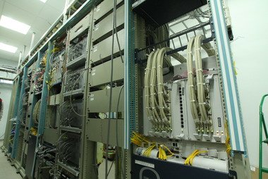
From the Base Station the call goes to the controller. It looks as boring as the BS itself - it’s just a set of cabinets:
7. 
Depending on the equipment, the controller can serve up to 60 Base Stations. Communication between the BS and the controller (BSC) can be carried out via a radio relay channel or via optics. The controller controls the operation of radio channels, incl. controls the subscriber’s movement and signal transmission from one BS to another.
The switch looks much more interesting:
8. 
9. 
Each switch serves from 2 to 30 controllers. It occupies a large hall, filled with various cabinets with equipment:
10. 
11. 
12. 
The switch controls traffic. Remember the old movies where people first dialed the “girl”, and then she connected them to another subscriber by switching wires? Modern switches do the same thing:
13. 
To control the network, Beeline has several cars, which they affectionately call “hedgehogs.” They move around the city and measure the signal level of their own network, as well as the level of the network of colleagues from " Big Three":
14. 
The entire roof of such a car is covered with antennas:
15. 
Inside there is equipment that makes hundreds of calls and takes information:
16. 
24-hour monitoring of switches and controllers is carried out from the Mission Control Center of the Network Control Center (NCC):
17. 
There are 3 main areas for monitoring the cellular network: accident rates, statistics and Feedback from subscribers.
Just like in airplanes, all cellular network equipment has sensors that send a signal to the central control system and output information to dispatchers’ computers. If some equipment fails, the light on the monitor will begin to “blink.”
The CCS also tracks statistics for all switches and controllers. He analyzes it, comparing it with previous periods (hour, day, week, etc.). If the statistics of any of the nodes began to differ sharply from the previous indicators, then the light on the monitor will start to “blink” again.
Feedback is received by customer service operators. If they cannot resolve the problem, the call is transferred to a technician. If he turns out to be powerless, then an “incident” is created in the company, which is resolved by the engineers involved in the operation of the relevant equipment.
The switches are monitored 24/7 by 2 engineers:
18. 
The graph shows the activity of Moscow switches. It is clearly visible that almost no one calls at night:
19. 
Control over the controllers (forgive the tautology) is carried out from the second floor of the Network Control Center:
22. 
21. 
I understand that you still have a lot of questions about how the cellular network works. The topic is complex, and I asked a specialist from Beeline to help me respond to your comments. My only request is to stay on topic. And questions like “Beeline radishes. They stole 3 rubles from my account” - address subscriber service 0611.
Tomorrow there will be a post about how a whale jumped out in front of me, but I didn’t have time to photograph it. Stay Tuned!
It’s a little sad that the vast majority of people, when asked: “How does cellular communication work?” answer “over the air” or even “I don’t know.”
Continuing this topic, I had a funny conversation with a friend on the topic of mobile communications. This happened exactly a couple of days before what was celebrated by all signalmen and telecom workers "Radio Day" holiday. It so happened that due to his ardent life position, my friend believed that mobile communication works without wires at all via satellite. Exclusively due to radio waves. At first I couldn't convince him. But after a short conversation everything fell into place.
After this friendly “lecture,” the idea arose to write in simple language about how cellular communications work. Everything is as it is.
When you dial a number and start calling, or someone calls you, then your mobile phone communicates via radio channel from one of the antennas of the nearest base station. Where are these base stations, you ask?
pay attention to industrial buildings, urban high-rises and special towers. On them there are large gray rectangular blocks with protruding antennas of various shapes. But these antennas are not television or satellite, but transceiver cellular operators. They are directed in different directions to provide communication to subscribers from all directions. After all, we don’t know where the signal will come from and where the unfortunate subscriber with the handset will take us? In professional jargon, antennas are also called “sectors”. As a rule, they are set from one to twelve.
From the antenna the signal is transmitted via cable directly to the station control unit. Together they form the base station [antennas and control unit]. Several base stations, whose antennas serve a separate area, for example, a city district or a small town, are connected to a special unit - controller. Up to 15 base stations are usually connected to one controller.


In turn, the controllers, of which there may also be several, are connected by cables to the “think tank” - switch. The switch provides output and input of signals to city telephone lines, to other cellular operators, as well as long-distance and international communications.
In small networks, only one switch is used, in larger ones, serving more than a million subscribers at once, two, three or more switches can be used, again interconnected by wires.
Why such complexity? Readers will ask. It would seem that, you can simply connect the antennas to the switch and everything will work. And here are base stations, switches, a bunch of cables... But it’s not so simple.

When a person moves along the street on foot or by car, train, etc. and at the same time talking on the phone, it is important to ensure continuity of communication. Signalmen process of relay handover in mobile networks called the term "handover". It is necessary to timely switch the subscriber's phone from one base station to another, from one controller to another, and so on.
If the base stations were directly connected to the switch, then all these switching would have to be managed by the switch. And the “poor” guy already has something to do. The multi-level network design makes it possible to evenly distribute the load across technical means . This reduces the likelihood of equipment failure and resulting loss of communication. After all, we all interested in uninterrupted communication, right?
So, having reached the switch, our call is transferred to then - to the network of another mobile operator, city long-distance and international communications. Of course, this happens over high-speed cable channels communications. The call arrives at the switchboard another operator. At the same time, the latter “knows” in which territory [in the coverage area, which controller] the desired subscriber is currently located. The switch transmits telephone call to a specific controller, which contains information in the coverage area of which base station the call recipient is located. The controller sends a signal to this single base station, and it, in turn, “interrogates”, that is, calls the mobile phone. A tube starts ringing strangely.
This whole long and complex process actually takes 2-3 seconds!
Exactly the same thing happens phone calls to different cities of Russia, Europe and the world. For contact switches of various telecom operators use high-speed fiber optic communication channels. Thanks to them, a telephone signal travels hundreds of thousands of kilometers in a matter of seconds.
Thanks to the great Alexander Popov for giving the world radio! If it weren’t for him, perhaps we would now be deprived of many of the benefits of civilization.
