Do-it-yourself peak programmer. Homemade programmer for PIC controllers. Features of practical use
So, we made up our minds and decided to assemble our first homemade product on a microcontroller, all that remains is to understand how to program it. Therefore, we will need a PIC programmer, and you can assemble its circuit yourself; let’s look at a few simple designs as an example.
The circuit allows you to program microcontrollers and EEPROM memory I2C.
List of supported microcontrollers, subject to joint use with the IC-PROG v1.05D utility:
Microcontrollers from Microchip: PIC12C508, PIC12C508A, PIC12C509, PIC12C509A, PIC12CE518, PIC12CE519, PIC12C671, PIC12C672, PIC12CE673, PIC12CE674, PIC12F629, PIC12F675, PIC16C433, PIC16C 61, PIC16C62A, PIC16C62B, PIC16C63, PIC16C63A, PIC16C64A, PIC16C65A, PIC16C65B, PIC16C66, PIC16C67, PIC16C71, PIC16C72, PIC16C72A, PIC16C73A, PIC16C73B, PIC16C74A, PIC16C74B, PIC16C76, PIC16C77, PIC16F72, PIC16F73, PIC16F74, PIC16F76, PIC16F77, PIC16C84, PIC16F83, PIC16F84 , PIC16F84A, PIC16F88, PIC16C505*, PIC16C620, PIC16C620A, PIC16C621, PIC16C621A, PIC16C622, PIC16C622A, PIC16CE623 , PIC16CE624, PIC16CE625, PIC16F627, PIC16F628, PIC16F628A, PIC16F630*, PIC16F648A, PIC16F676*, PIC16C710, PIC16C711, PIC16C712, PIC16C715, PIC16C716, P IC16C717, PIC16C745, PIC16C765, PIC16C770*, PIC16C771*, PIC16C773, PIC16C774, PIC16C781*, PIC16C782* , PIC16F818, PIC16F819, PIC16F870, PIC16F871, PIC16F872, PIC16F873, PIC16F873A, PIC16F874, PIC16F874A, PIC16F876, PIC16F876A, PIC16F877, PIC16F877A, P IC16C923*, PIC16C924*, PIC18F242, PIC18F248, PIC18F252, PIC18F258, PIC18F442, PIC18F448, PIC18F452, PIC18F458, PIC18F1220 , PIC18F1320, PIC18F2320, PIC18F4320, PIC18F4539, PIC18F6620*, PIC18F6720*, PIC18F8620*, PIC18F8720*
Note: microcontrollers marked with an asterisk (*) must be connected to the programmer via an ICSP connector.
Serial EEPROM I2C memory(IIC): X24C01, 24C01A, 24C02, 24C04, 24C08, 24C16, 24C32, 24C64, AT24C128, M24C128, AT24C256, M24C256, AT24C512.

Install the microcircuit into the socket, strictly observing the position of the key. Connect the cord, turn on the power. Launch the IC-PROG program. Select your PIC microcontroller from the dropdown list.
If you don’t have the firmware, make it: to do this, open the standard Notepad program or any other editor; insert the text of the firmware into the document; save under any name with *.txt or *.hex extension.
Then in the utility in IC-PROG File >> Open file >> find our file with the firmware. Window " Program code" must be filled in with different codes.
In the IC-PROG window, click “Program the chip” and the red LED on the device diagram lights up. Programming takes approximately 30 seconds. To check, select - Compare chip with buffer.
An alternative version of the EXTRA-PIC programmer circuit from a ready-made printed circuit board in Sprint Layout you can open it from the green link above.
PIC microcontrollers have earned fame due to their unpretentiousness and quality of operation, as well as versatility in use. But what can a microcontroller do without the ability to write new programs onto it? Without a programmer, this is nothing more than a piece of amazingly shaped hardware. The PIC programmer itself can be of two types: either home-made or factory-made.
The difference between factory and homemade programmers
First of all, they are distinguished by the reliability and functionality that they provide to microcontroller owners. So, if you make a homemade one, then, as a rule, it is designed for only one model of PIC microcontroller, while the programmer from Microchip provides the ability to work with various types, modifications and models of microcontrollers.
Factory programmer from Microchip

The most famous and popular is the simple PIC programmer, which is used by many people and is known to many as PICkit 2. Its popularity is due to its obvious and hidden advantages. The obvious advantages that this has USB programmer for PIC, it is possible to list for a long time, among them: relatively low cost, ease of operation and versatility relative to the entire family of microcontrollers, ranging from 6-pin to 20-pin.
Using a programmer from Microchip
You can find many tutorials on its use that will help you understand all sorts of aspects of its use. If we consider not only a PIC programmer purchased second-hand, but purchased from an official representative, then we can also notice the quality of support provided with it. So, in addition there are training materials on use, licensed development environments, as well as a demo board, which is designed to work with low-pin microcontrollers. In addition to all this, there are utilities that will make working with the mechanism more enjoyable and will help monitor the process of programming and debugging the microcontroller. A utility is also supplied to stimulate the operation of the MK.

Other programmers
In addition to the official programmer, there are others that allow you to program microcontrollers. When purchasing them, you don’t have to count on additional software, but for those who don’t need more, this is enough. A rather obvious disadvantage is that for some programmers it can be difficult to find necessary provision to be able to do quality work.
Manually assembled programmers
And now, perhaps, the most interesting thing is the PIC controller programmers, which are assembled manually. This option is used by those who do not have money or simply do not want to spend it. If you purchase from an official representative, you can count on the fact that if the device turns out to be of poor quality, you can return it and get a new one in exchange. And when buying “from hand” or using bulletin boards in case of poor-quality soldering or mechanical damage You can’t count on reimbursement of expenses and receiving a quality programmer. Now let's move on to the hand-assembled electronics.
The PIC programmer can be designed for specific models or be universal (for all or almost all models). They are assembled on microcircuits that can convert signals from the RS-232 port into a signal that will allow programming the MK. You need to remember that when you assemble a design given by someone, the PIC programmer, the circuit and the result must match one to one. Even small deviations are undesirable. This remark applies to beginners in electronics; people with experience and practice can improve almost any circuit if there is room for improvement.

It’s also worth saying a word about the software package that is provided by the USB programmer for PIC, assembled with your own hands. The fact is that it is not enough to assemble the programmer itself according to one of the many schemes presented on the world wide web. You also need software that will allow the computer to flash the microcontroller with its help. Icprog, WinPic800 and many other programs are often used as such. If the author of the programmer circuit himself did not indicate the software with which his creation can do its job, then you will have to find out yourself by brute force. The same applies to those who assemble their own circuits. You can write a program for MK yourself, but this is real aerobatics.
Universal programmers that are suitable not only for RIS
If a person is interested in programming microcontrollers, then it is unlikely that he will constantly use only one type. For those who do not want to buy separate programmers for various types microcontrollers from various manufacturers, universal devices have been developed that can program MCUs from several companies. Since there are quite a few companies producing them, it’s worth choosing a couple and talking about the programmers for them. The choice fell on the giants of the microcontroller market: PIC and AVR.

The universal PIC and AVR programmer is equipment whose peculiarity lies in its versatility and the ability to change the operation thanks to the program without making changes to the hardware component. Thanks to this property, such devices easily work with microcontrollers that were released for sale after the release of the programmer. Considering that the architecture will not change significantly in the near future, they will be suitable for use for a long time. Additional pleasant properties of factory programmers include:
- Significant hardware restrictions on the number of programmable microcircuits, which will allow programming not one, but several pieces of electronics at once.
- Possibility of programming microcontrollers and circuits based on various technologies (NVRAM, NAND Flash and others).
- Relatively short programming time. Depending on the programmer model and the complexity of the programmed code, it may take from 20 to 400 seconds.
Features of practical use

Separately, it is worth touching on the topic of practical use. As a rule, programmers are connected to USB ports, but there are also variations that work using the same wires as the hard drive. And to use them you will have to remove the computer cover, sort out the wires, and the connection process itself is not very convenient. But the second type is more versatile and powerful, thanks to it the firmware speed is faster than when connected via USB. Using the second option does not always seem to be such a convenient and comfortable solution as with USB, because before using it you need to do a number of operations: take out the case, open it, find the necessary wire. You don’t have to worry about possible problems from overheating or power surges when working with factory models, since they usually have special protection.
Working with microcontrollers
What is necessary for all programmers with microcontrollers to work? The fact is that, although the programmers themselves are independent circuits, they transmit computer signals to a certain sequence. And the problem of how to explain to the computer what exactly needs to be sent is solved by the programmer software.
Quite a lot is freely available various programs, which are aimed at working with programmers, both home-made and factory-made. But if it is manufactured by a little-known company, was made according to the design of another electronics enthusiast, or by the person reading these lines himself, then the software may not be found. In this case, you can use a search of all available programming utilities, and if none of them work (if you are sure that the programmer works well), then you need to either take/make another PIC programmer, or write your own program, which is a very high level of pilotage.

Possible problems
Alas, even the most ideal technology is not without possible problems, which no, no, and will arise. For improved understanding, it is necessary to make a list. Some of these problems can be corrected manually with a detailed inspection of the programmer, others can only be checked if you have the necessary testing equipment. In this case, if the PIC microcontroller programmer is factory-made, it is unlikely to be repaired. Although you can try to find possible reasons failures:
- Poor quality soldering of programmer elements.
- Lack of drivers to work with the device.
- Damage inside the programmer or wires inside the computer/USB.
Experiments with microcontrollers
So, everything is there. How to start working with equipment, how to start flashing a microcontroller with a programmer?
- To plug external power supply, connect all equipment.
- Initially, an environment is needed with the help of which everything will be done.
- Create the required project, select the microcontroller configuration.
- Prepare a file containing all the necessary code.
- Connect to the programmer.
- When everything is ready, you can flash the microcontroller.
Above, only a general diagram was written, which allows you to understand how the process occurs. It may differ slightly for individual development environments, and more detailed information about them can be found in the instructions.
I would like to write a separate appeal to those who are just starting to use programmers. Remember that, no matter how basic some steps may seem, you must always adhere to them so that the equipment can work normally and adequately and perform the tasks you set. Good luck in electronics!

What first steps should a radio amateur take if he decides to assemble a circuit on a microcontroller? Naturally, a control program is needed - “firmware”, as well as a programmer.
And if there are no problems with the first point - the finished “firmware” is usually uploaded by the authors of the circuits, then with the programmer things are more complicated.
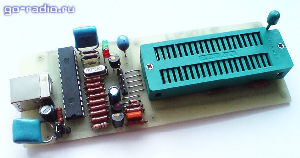
The price of ready-made USB programmers is quite high and the best solution will assemble it yourself. Here is a diagram of the proposed device (pictures are clickable).
Main part.

MK installation panel.

The original diagram was taken from the LabKit.ru website with the permission of the author, for which many thanks to him. This is a so-called clone of the proprietary PICkit2 programmer. Since the device version is a “lightweight” copy of the proprietary PICkit2, the author called his development PICkit-2 Lite, which emphasizes the ease of assembly of such a device for beginner radio amateurs.
What can a programmer do? Using the programmer, you can flash most readily available and popular PIC series MCUs (PIC16F84A, PIC16F628A, PIC12F629, PIC12F675, PIC16F877A, etc.), as well as 24LC series EEPROM memory chips. In addition, the programmer can operate in USB-UART converter mode and has some of the functions of a logic analyzer. A particularly important function that the programmer has is the calculation of the calibration constant of the built-in RC generator of some MCUs (for example, such as PIC12F629 and PIC12F675).
Necessary changes.
There are some changes in the circuit that are necessary so that using the PICkit-2 Lite programmer it is possible to write/erase/read data from EEPROM memory chips of the 24Cxx series.
From the changes that were made to the scheme. Added connection from pin 6 of DD1 (RA4) to pin 21 of the ZIF panel. The AUX pin is used exclusively for working with 24LC EEPROM memory chips (24C04, 24WC08 and analogues). It transmits data, which is why it is marked with the word “Data” on the programming panel diagram. When programming microcontrollers, the AUX pin is usually not used, although it is needed when programming MKs in LVP mode.
A 2 kOhm pull-up resistor has also been added, which is connected between the SDA and Vcc pins of the memory chips.
I already made all these modifications on the printed circuit board, after assembling PICkit-2 Lite according to original diagram author.
24Cxx memory chips (24C08, etc.) are widely used in household radio equipment, and sometimes they have to be flashed, for example, when repairing CRT TVs. They use 24Cxx memory to store settings.
LCD TVs use a different type of memory (Flash memory). I have already talked about how to flash the memory of an LCD TV. If anyone is interested, take a look.
Due to the need to work with 24Cxx series microcircuits, I had to “finish” the programmer. I didn’t etch a new printed circuit board, I just added necessary elements on the printed circuit board. This is what happened.

The core of the device is a microcontroller PIC18F2550-I/SP.

This is the only chip in the device. MK PIC18F2550 needs to be “flashed”. This simple operation It causes stupor for many, as the so-called “chicken and egg” problem arises. I’ll tell you how I solved it a little later.
List of parts for assembling the programmer. IN mobile version drag the table to the left (swipe left-right) to see all its columns.
| Name | Designation | Rating/Parameters | Brand or item type |
| For the main part of the programmer | |||
| Microcontroller | DD1 | 8-bit microcontroller | PIC18F2550-I/SP |
| Bipolar transistors | VT1, VT2, VT3 | KT3102 | |
| VT4 | KT361 | ||
| Diode | VD1 | KD522, 1N4148 | |
| Schottky diode | VD2 | 1N5817 | |
| LEDs | HL1, HL2 | any 3 volt, red And green glow colors | |
| Resistors | R1, R2 | 300 Ohm | |
| R3 | 22 kOhm | ||
| R4 | 1 kOhm | ||
| R5, R6, R12 | 10 kOhm | ||
| R7, R8, R14 | 100 Ohm | ||
| R9, R10, R15, R16 | 4.7 kOhm | ||
| R11 | 2.7 kOhm | ||
| R13 | 100 kOhm | ||
| Capacitors | C2 | 0.1 μ | K10-17 (ceramic), imported analogues |
| C3 | 0.47 microns | ||
| Electrolytic capacitors | C1 | 100uF * 6.3V | K50-6, imported analogues |
| C4 | 47 uF * 16 V | ||
| Inductor (choke) | L1 | 680 µH | unified type EC24, CECL or homemade |
| Quartz resonator | ZQ1 | 20 MHz | |
| USB socket | XS1 | type USB-BF | |
| Jumper | XT1 | any type of "jumper" | |
| For microcontroller installation panel (MK) | |||
| ZIF panel | XS1 | any 40-pin ZIF panel | |
| Resistors | R1 | 2 kOhm | MLT, MON (power from 0.125 W and above), imported analogues |
| R2, R3, R4, R5, R6 | 10 kOhm | ||
Now a little about the details and their purpose.
Green LED HL1 lights up when power is applied to the programmer, and red The HL2 LED emits when data is transferred between the computer and the programmer.
To give the device versatility and reliability, an XS1 type “B” (square) USB socket is used. The computer uses a Type A USB socket. Therefore, it is impossible to mix up the sockets of the connecting cable. This solution also contributes to the reliability of the device. If the cable becomes unusable, it can be easily replaced with a new one without resorting to soldering or installation work.
As a 680 µH inductor L1, it is better to use a ready-made one (for example, types EC24 or CECL). But if you can’t find a finished product, you can make the throttle yourself. To do this, you need to wind 250 - 300 turns of PEL-0.1 wire onto a ferrite core from a CW68 type inductor. It is worth considering that due to the presence of PWM with feedback, there is no need to worry about the accuracy of the inductance rating.
The voltage for high voltage programming (Vpp) from +8.5 to 14 volts is created by the key regulator. It includes elements VT1, VD1, L1, C4, R4, R10, R11. PWM pulses are sent from pin 12 of the PIC18F2550 to the VT1 base. Feedback carried out by the divider R10, R11.
To protect circuit elements from reverse voltage from the programming lines, when using a USB programmer in the ICSP (In-Circuit Serial Programming) mode, a VD2 diode is used. VD2 is a Schottky diode. It should be selected with a voltage drop of P-N junction no more than 0.45 volts. Also, the VD2 diode protects elements from reverse voltage when the programmer is used in USB-UART conversion and logic analyzer mode.
When using the programmer exclusively for programming microcontrollers in the panel (without using ICSP), you can eliminate the VD2 diode completely (this is what I did) and install a jumper instead.
The compactness of the device is made by the universal ZIF panel (Zero Insertion Force - with zero installation effort).

Thanks to it, you can “hardwire” a microcontroller into almost any DIP package.
The diagram "Microcontroller (MK) installation panel" indicates how microcontrollers with different housings must be installed in the panel. When installing the MK, you should pay attention to the fact that the microcontroller in the panel is positioned so that the key on the chip is on the side of the ZIF panel locking lever.
This is how you need to install 18-pin microcontrollers (PIC16F84A, PIC16F628A, etc.).

And here are 8-pin microcontrollers (PIC12F675, PIC12F629, etc.).

If there is a need to flash a microcontroller in a housing for surface mount(SOIC), then you can use an adapter or simply solder 5 pins to the microcontroller, which are usually required for programming (Vpp, Clock, Data, Vcc, GND).

Finished drawing printed circuit board with all changes you will find the link at the end of the article. By opening the file in the Sprint Layout 5.0 program, using the “Print” mode, you can not only print a layer with a pattern of printed conductors, but also view the positioning of elements on the printed circuit board. Pay attention to the isolated jumper that connects pin 6 of DD1 and pin 21 of the ZIF panel. You need to print the board drawing in mirror image.
You can make a printed circuit board using the LUT method, as well as a marker for printed circuit boards, using tsaponlak (this is what I did) or the “pencil” method.

Here is a picture of the positioning of elements on a printed circuit board (clickable).

When installing, the first step is to solder jumpers made of tinned copper wire, then install low-profile elements (resistors, capacitors, quartz, ISCP pin connector), then transistors and a programmed MK. The last step is to install the ZIF panel, USB socket and seal the wires in insulation (jumpers).
"Firmware" of the PIC18F2550 microcontroller.
Firmware file - PK2V023200.hex you need to write the PIC18F2550I-SP MK into the memory using any programmer that supports PIC microcontrollers (for example, Extra-PIC). I used the JDM Programmator JONIC PROG and the program WinPic800.

You can upload the firmware to the PIC18F2550 MCU using the same proprietary programmer PICkit2 or its new version PICkit3. Naturally, you can do this with a homemade PICkit-2 Lite, if one of your friends managed to assemble it before you :).
It is also worth knowing that the “firmware” of the PIC18F2550-I/SP microcontroller (file PK2V023200.hex) is written when installing the PICkit 2 Programmer program in a folder along with the files of the program itself. Approximate location of the file PK2V023200.hex - "C:\Program Files (x86)\Microchip\PICkit 2 v2\PK2V023200.hex" . For those who have 32-bit installed on their PC Windows version, the location path will be different: "C:\Program Files\Microchip\PICkit 2 v2\PK2V023200.hex" .
Well, if you couldn’t solve the “chicken and egg” problem using the proposed methods, then you can buy a ready-made PICkit3 programmer on the AliExpress website. It costs much cheaper there. I wrote about how to buy parts and electronic kits on AliExpress.
Updating the programmer firmware.
Progress does not stand still and from time to time Microchip releases updates for its software, including for the PICkit2, PICkit3 programmer. Naturally, we can update control program his homemade PICkit-2 Lite. To do this you will need the PICkit2 Programmer program. What it is and how to use it - a little later. In the meantime, a few words about what needs to be done to update the firmware.
To update the programmer software, you must close jumper XT1 on the programmer when it is disconnected from the computer. Then connect the programmer to the PC and launch PICkit2 Programmer. When XT1 is closed, the mode is activated bootloader to download the new firmware version. Then in PICkit2 Programmer, through the menu “Tools” - “Download PICkit 2 Operation System”, open the previously prepared hex file of the updated firmware. Next, the programmer software update process will occur.
After the update, you need to disconnect the programmer from the PC and remove the XT1 jumper. IN normal mode jumper open. You can find out the programmer software version through the "Help" - "About" menu in the PICkit2 Programmer program.
This is all about technical issues. And now about the software.
Working with the programmer. PICkit2 Programmer.
To work with the USB programmer, we will need to install the PICkit2 Programmer program on the computer. This special program has simple interface, easy to install and does not require special configuration. It is worth noting that you can work with the programmer using the MPLAB IDE development environment, but in order to flash/erase/read the MK, a simple program - PICkit2 Programmer is enough. I recommend.
After installing the PICkit2 Programmer program, we connect the assembled USB programmer to the computer. At the same time it will light up green LED ("power"), and operating system recognizes the device as "PICkit2 Microcontroller Programmer" and install the drivers.
Launch the PICkit2 Programmer program. An inscription should appear in the program window.

If the programmer is not connected, a scary message will appear in the program window and brief instructions"What to do?" in English.

If the programmer is connected to a computer with an MK installed, the program will detect it when launched and will notify us about it in the PICkit2 Programmer window.

Congratulations! The first step has been taken. And I talked about how to use the PICkit2 Programmer program in a separate article. Next step .
Required files:
PICkit2 User Manual (Russian) take or.
The development of electronics is proceeding at a rapid pace, and increasingly the main element of a device is a microcontroller. It does the bulk of the work and frees the designer from the need to create sophisticated circuit designs, thereby reducing the size of the printed circuit board to a minimum. As everyone knows, a microcontroller is controlled by a program written in its internal memory. And if an experienced electronics programmer has no problems using microcontrollers in his devices, then for a novice radio amateur, trying to write a program into a controller (especially a PIC) can result in great disappointment, and sometimes even a small pyrotechnic show in the form of a smoking chip.
Oddly enough, for all the greatness of the Internet, there is very little information about the firmware PIC controllers, and the material that can be found is of very dubious quality. Of course, you can buy a factory programmer for an inadequate price and sew to your heart’s content, but what to do if a person is not engaged in mass production. For these purposes, you can assemble a simple and inexpensive homemade product called JDM programmer according to the diagram below (Figure No. 1):

Figure No. 1 - programmer circuit
I’ll immediately provide a list of elements for those who are too lazy to look closely at the diagram:
- R1 - 10 kOhm
- R2 - 10 kOhm (trimmed). By adjusting the resistance of this resistor, you need to achieve about 13V at pin No. 4 (VPP) during programming. In my case the resistance is 1.2 kOhm
- R3 - 200 Ohm
- R4, R5 - 1.5 kOhm
- VD1, VD2, VD3, VD4, VD6 - 1N4148
- VD5 - 1N4733A (Stabilization voltage 5.1V)
- VD7 - 1N4743A (Stabilization voltage 13V)
- C1 - 100 nF (0.1 µF)
- C2 - 470 uF x 16 V (electrolytic)
- SUB-D9F - COM port connector (MAMA or SOCKET)
- DIP8 socket - depends on the controller you use
The diagram uses an example of connecting such common controllers as PIC12F675 And PIC12F629, but this does not mean at all that the firmware of other series PIC will be impossible. To write a program to a controller of another type, just connect the wires of the programmer in accordance with Figure 2, which is shown below.

Figure No. 2 - options for PIC controller housings with the necessary pins
As you might guess, the circuit of my programmer uses a housing DIP8. If you really want, you can make a universal adapter for each type of microcircuit, thereby obtaining a universal programmer. But since PIC controllers I rarely work, this is enough for me.
Although the circuit itself is quite simple and will not cause difficulties in assembly, it also requires respect. Therefore, it would be nice to make a printed circuit board for it. After some manipulations with the program SprintLayout, PCB, drill and iron, such a blank was born (photo No. 3).

Photo No. 3 - programmer circuit board
Download the PCB source for the program SprintLayout you can follow this link:
(downloads: 670)
If desired, you can change it to suit your type of PIC controller. For those who decided to leave the board unchanged, I am posting a view from the parts side to facilitate installation (Figure No. 4).

Figure No. 4 - board from the mounting side
A little more witchcraft with a soldering iron and we have a ready-made device capable of flashing PIC controller through COM port your computer. The result of my efforts, still warm and not washed off from the flux, is shown in photo No. 5.

Photo No. 5 - assembled programmer
From now on, the first stage on the way to firmware PIC controller, has come to an end. The second stage will include connecting the programmer to the computer and working with the program IC-Prog.
Unfortunately, not all modern computers and laptops are able to work with this programmer due to the banal absence of COM ports, and those that are installed on laptops do not provide the necessary for programming 12V. So I decided to turn to my first PC, which had been gathering dust a long time ago and was waiting for its finest hour (and finally did).
So, turn on the computer and first of all install the program IC-Prog. You can download it from the author’s website or from this link:
(downloads: 769)
We connect the programmer to COM port and just launched installed application. For correct operation it is necessary to perform a number of manipulations. Initially, you need to select the type of controller that you are going to sew. I have this PIC12F675. In screenshot No. 6, the field for selecting a controller is highlighted in red.

Screenshot No. 6 - selecting the type of microcontroller

Screenshot No. 7 - setting up the controller recording method
In the same window, go to the "tab" Programming" and select the item " Check during programming". Checking after programming may cause an error, since in some cases the firmware itself sets read blocking fuses SR. So as not to fool yourself this check It's better to turn it off. In short, we follow screenshot No. 8.

Screenshot No. 8 - setting up verification
Let's continue working with this window and go to the " tab Are common". Here you need to set the priority of the program and be sure to use NT/2000/XP driver (screenshot No. 9). In some cases, the program may prompt you to install of this driver and a restart will be required IC-Prog.

Screenshot No. 9 - general settings
So, we're done with this window. Now let's move on to the settings of the programmer itself. Select from the menu " Settings"->"Programmer settings"or just press the key F3. The following window appears, shown in screenshot No. 10.

Screenshot No. 10 - programmer settings window
First of all, select the type of programmer - JDM Programmer. Next, set the radio button for using the driver Windows. The next step involves choosing COM port, to which your programmer is connected. If there is only one, there are no questions at all, but if there is more than one, look in the device manager which one is currently in use. The I/O latency slider is designed to adjust the write and read speed. This may be needed on fast computers and if problems arise with the firmware - this parameter must be increased. In my case, it remained equal by default 10 and everything worked fine.
That's it for setting up the program. IC-Prog is over and you can move on to the process of the firmware itself, but first we read the data from the microcontroller and see what is written to it. To do this, on the toolbar, click on the microcircuit icon with a green arrow, as shown in screenshot No. 11.

Screenshot No. 11 - the process of reading information from the microcontroller
If the microcontroller is new and has not been flashed before, then all its memory cells will be filled with values 3FFF, except the very last one. It will contain the value of the calibration constant. This is a very important and unique value for each controller. The timing accuracy depends on it, which is set by the manufacturer by selecting and setting this same constant. Screenshot No. 12 shows the memory cell in which the constant will be stored when reading the controller.

Screenshot No. 12 - the value of the calibration constant
I repeat that the value is unique for each chip and does not have to match what is shown in the figure. Many people, due to inexperience, overwrite this constant and subsequently PIC controller starts to work incorrectly if the project uses clocking from an internal oscillator. I advise you to write down this constant and stick a label with its value directly on the controller. This way you will avoid a lot of troubles in the future. So, the value is written down - let's move on. We open the firmware file, which usually has the extension .hex. Now instead of inscriptions 3FFF, the programming buffer contains the code of our program (screenshot No. 13).

Screenshot No. 13 - firmware loaded into the programming buffer
I wrote above that many people inadvertently overwrite the calibration constant. When does this happen? This happens when the firmware file is opened. The constant value automatically changes to 3FFF and once you start the programming process, there is no turning back. In screenshot No. 14, the memory cell where the constant was previously is highlighted 3450 (before opening hex file).
Currently there are many circuit diagrams using various microcontrollers, including PIC microcontrollers from MicroChip. This made it possible to obtain quite functional devices, despite their simplicity.
But the operation of the microcontroller is impossible without a control program that must be written down. In this article we will look at the universal PIC programmer— EXTRA-PIC allows you to program PIC controllers and EEPROM I2C memory via a COM port or via .
List of supported chips when used with the IC-PROG v1.05D program:
Microchip PIC controllers: PIC12C508, PIC12C508A, PIC12C509, PIC12C509A, PIC12CE518, PIC12CE519, PIC12C671, PIC12C672, PIC12CE673, PIC12CE674, PIC12F629, PIC12F675, PIC1 6C433, PIC16C61, PIC16C62A, PIC16C62B, PIC16C63, PIC16C63A, PIC16C64A, PIC16C65A, PIC16C65B, PIC16C66, PIC16C67, PIC16C71, PIC16C72, PIC16C72A, PIC16C73A, PIC16C73B, PIC16C74A, PIC16C74B, PIC16C76, PIC16C77, PIC16F72, PIC16F73, PIC16F74, PIC16F76, PIC16F77 , PIC16C84, PIC16F83, PIC16F84, PIC16F84A, PIC16F88, PIC16C505*, PIC16C620, PIC16C620A, PIC16C621, PIC16C621A , PIC16C622, PIC16C622A, PIC16CE623, PIC16CE624, PIC16CE625, PIC16F627, PIC16F628, PIC16F628A, PIC16F630*, PIC16F648A, PIC16F676*, PIC16C710, PIC16C711, PIC16C712, PIC16C715, PIC16C716, PIC16C717, PIC16C745, PIC16C765, PIC16C770*, PIC16C771*, PIC16C773, PIC16C774 , PIC16C781*, PIC16C782*, PIC16F818, PIC16F819, PIC16F870, PIC16F871, PIC16F872, PIC16F873, PIC16F873A, PIC16F874, PIC16F874A, PIC16F876, PIC16F876A, PIC16F877, PIC16F877A, PIC16C923*, PIC16C924*, PIC18F242, PIC18F248, PIC18F252, PIC18F258, PIC18F442, PIC18F448 , PIC18F452, PIC18F458, PIC18F1220, PIC18F1320, PIC18F2320, PIC18F4320, PIC18F4539, PIC18F6620*, PIC18F6720*, PIC18F8620*, PIC18F8720*
Note: microcontrollers marked with an asterisk (*) must be connected to the programmer via an ICSP connector.
Serial EEPROM I2C (IIC): X24C01, 24C01A, 24C02, 24C04, 24C08, 24C16, 24C32, 24C64, AT24C128, M24C128, AT24C256, M24C256, AT24C512.
The EXTRA-PIC programmer circuit itself:
The programmable controller is connected via connector X3. Below is the pinout of programming pins for different controllers:

And now instructions on how to program the microcontroller.
As an example, let's take the PIC16F876A microcontroller.
Assemble the programmer and prepare a power supply with output voltage no less 15V
Unpack the program into a separate directory. The created directory should contain three files:
icprog.exe— programmer shell file;
icprog.sys— driver required to work under Windows NT, 2000, XP. This file must always be located in the program directory;
icprog.chm- Help file.
Setting up the IC-PROG v1.05D program.
| For Windows95, 98, ME | For Windows NT, 2000, XP |
| (Windows XP only
): Right-click on the icprog.exe file. « Properties» >> tab « Compatibility » >> Place a check mark on " Run the program in compatibility mode for:" >> select " Windows 2000 «. |
|
|
|
« Settings » >> « Programmer «.  Check the settings, select the COM port you are using, click " Ok «. Check the settings, select the COM port you are using, click " Ok «.
|
|
| Further, " Settings » >> « Options" >> select the tab " Are common" >> check the box " On NT/2000/XP driver" >> Click " Ok » >> if the driver has not been installed on the system before, in the window that appears, “ Confirm» click « Ok". The driver will be installed and the programmer shell will restart. |
|
| Note: For very “fast” computers, you may need to increase the “ I/O Latency". Increasing this parameter increases the reliability of programming; however, the time spent on programming the chip also increases. | |
| « Settings » >> « Options" >> select the tab " I2C">> check the boxes:" Enable MCLR as VCC" And " Enable block recording". Click " Ok «. | |
| The program is ready to use. | |
Install the chip into the programmer panel, observing the position of the key.
Connect the extension cord, turn on the power.
Launch the IC-PROG program.
Select the PIC16F876A controller from the drop-down list.

If you do not have the firmware file, prepare it:
open the standard Notepad program;
insert the text of the firmware into the document;
save under any name, for example, prohivka.txt (extension *.txt or *.hex).
Next to IC-PROG File >> Open file(! not to be confused with Open data file) >> find our file with the firmware (if we have a file with the extension *.txt, then select in the file type Any File *.* ). The “Program code” window should be filled with information.
Press the “Program chip” button (the red LED lights up).
We wait for programming to complete (about 30 seconds).
To control, click “Compare chip with buffer”.
