Homemade lanterns with your own hands. Let's make an LED flashlight together with our own hands. Necessary elements for manufacturing
The first version of the flashlight circuit
In tests, this circuit showed incredible stability within the supply voltage of 3.7-14 volts (but be aware that as the voltage increases, the efficiency decreases). As I set the output to 3.7 volts, it was the same throughout the entire voltage range (we set the output voltage with resistor R3, as this resistance decreases, the output voltage increases, but I do not advise reducing it too much; if you are experimenting, calculate the maximum current on LED1 and the maximum voltage on the second) . If we power this circuit from Li-ion batteries, then the efficiency is approximately 87-95%. You may ask, why was PWM invented then? If you don't believe me, do the math yourself.
At 4.2 volts efficiency = 87%. At 3.8 volts efficiency = 95%. P =U*I
The LED consumes 0.7A at 3.7 volts, which means 0.7*3.7=2.59 W, subtract the voltage of the charged battery and multiply by the current consumption: (4.2 - 3.7) * 0.7 = 0.35W. Now we find out the efficiency: (100/(2.59+0.37)) * 2.59 = 87.5%. And half a percent for heating the remaining parts and tracks. Capacitor C2 - soft start for safe LED switching and protection against interference. Necessarily powerful LED install on a radiator, I used one radiator from a computer power supply. Variant of parts arrangement:

The output transistor should not touch the back metal wall to the board; insert paper between them or draw a drawing of the board on a sheet of notebook and make it the same as on the other side of the sheet. To power the LED flashlight, I used two Li-ion batteries from a laptop battery, but it is quite possible to use telephone batteries; it is desirable that their total current be 5-10A*h (connected in parallel).
Let's move on to the second version of the diode flashlight

I sold the first flashlight and felt that without it at night it was a little annoying, and there were no parts to repeat the previous scheme, so I had to improvise from what was available at that moment, namely: KT819, KT315 and KT361. Yes, even with such parts, it is possible to assemble a low-voltage stabilizer, but with slightly higher losses. The scheme resembles the previous one, but in this one everything is completely opposite. Capacitor C4 here also smoothly supplies voltage. The difference is that here the output transistor is opened by resistor R1 and KT315 closes it to a certain voltage, while in the previous circuit the output transistor is closed and opens second. Variant of parts arrangement:

I used it for about six months until the lens cracked, damaging the contacts inside the LED. It still worked, but only three cells out of six. Therefore, I left it as a gift :) Now I’ll tell you why the stabilization using an additional LED is so good. For those who are interested, read it, it may be useful when designing low-voltage stabilizers, or skip it and move on to the last option.
So, let's start with temperature stabilization; whoever conducted the experiments knows how important this is in winter or summer. So, in these two powerful flashlights The following system operates: as the temperature increases, the semiconductor channel increases, allowing passage more electrons than usual, so it seems that the channel resistance decreases and therefore the current passed through increases, since the same system operates on all semiconductors, the current through the LED also increases by closing all transistors to a certain level, that is, the stabilization voltage (experiments were carried out in the temperature range -21 ...+50 degrees Celsius). I collected many stabilizer circuits on the Internet and wondered “how could such mistakes be made!” Someone even recommended their own circuit for powering the laser, in which 5 degrees of temperature rise prepared the laser for ejection, so take this nuance into account!
Now about the LED itself. Anyone who has played with the supply voltage of LEDs knows that as it increases, the current consumption also increases sharply. Therefore, with a slight change in the output voltage of the stabilizer, the transistor (KT361) reacts many times more easily than with a simple resistor divider (which requires a serious gain), which solves all the problems of low-voltage stabilizers and reduces the number of parts.
Third version of LED flashlight
Let's proceed to the last scheme considered and used by me to this day. The efficiency is greater than in previous schemes, and the brightness of the glow is higher, and naturally, I bought an additional focus lens for the LED, and there are also 4 batteries, which approximately equals a capacity of 14A*hour. Principal el. scheme:

The circuit is quite simple and assembled in SMD design; there is no additional LED or transistors that consume excess current. For stabilization, TL431 is used and this is quite enough, the efficiency here is from 88 - 99%, if you don’t believe me, do the math. Photo of the finished homemade device:


Yes, by the way about brightness, here I allowed 3.9 volts at the output of the circuit and have been using it for more than a year, the LED is still alive, only the radiator is getting a little warm. But anyone who wants can set the supply voltage lower by selecting output resistors R2 and R3 (I advise you to do this on an incandescent lamp; when you get the result you want, connect the LED). Thank you for your attention, Levsha Lesha (Alexey Stepanov) was with you.
Discuss the article POWERFUL LED FLASHLIGHTS
LED light sources are by far the most popular among consumers. LED lights are especially popular. There are different ways to get an LED flashlight: you can buy it in a store or make it yourself.
LED handheld flashlight
Many people who understand at least a little electronics, for various reasons, increasingly prefer to make such lighting devices with their own hands. Therefore, this article will discuss several options for how you can make your own diode hand-held flashlight.
Advantages of LED lamps
Today, LED is considered one of the most profitable efficient light sources. It is capable of creating a bright luminous flux at low powers, and also has a lot of other positive technical characteristics.
It’s worth making your own flashlight from diodes for the following reasons:
- individual LEDs are not expensive;
- all aspects of assembly can be easily accomplished with your own hands;
- a homemade lighting device can run on batteries (two or one);
Note! Due to the low power consumption of LEDs during operation, there are many schemes where only one battery powers the device. If necessary, it can be replaced with a battery of appropriate dimensions.
- availability of simple diagrams for assembly.

LEDs and their glow
In addition, the resulting lamp will last much longer than its analogues. In this case, you can choose any color of the glow (white, yellow, green, etc.). Naturally, the most relevant colors here will be yellow and white. But, if you need to make special lighting for some celebration, then you can use LEDs with a more extravagant glow color.
Where can the lamp be used and features
Very often there is a situation when you need light, but there is no way to install a lighting system and stationary lighting fixtures. In such a situation, a portable lamp will come to the rescue. An LED hand-held flashlight, which can be made with one or more batteries, will find wide application in everyday life:
- it can be used for work in the garden;
- illuminate closets and other rooms where there is no lighting;
- use in a garage when inspecting a vehicle in an inspection pit.
Note! If desired, by analogy with a hand-held flashlight, you can make a lamp model that can be easily installed on any surface. In this case, the flashlight will no longer be portable, but a stationary source of light.
To do it yourself led flashlight manual type, you need to remember, first of all, the disadvantages of diodes. The truly widespread distribution of LED products is hampered by such shortcomings as the nonlinear current-voltage characteristic or current-voltage characteristic, as well as the presence of an “inconvenient” voltage for power supply. In this regard, all LED lamps contain special voltage converters that operate from inductive energy storage devices or transformers. In this regard, before you begin to independently assemble such a lamp with your own hands, you need to select the necessary diagram.
When planning to make a hand-held flashlight from LEDs, it is imperative to think about its power supply. You can make such a lamp using batteries (two or one).
Let's look at several options for how to make a diode hand-held flashlight.
Circuit with super-bright LED DFL-OSPW5111Р
This circuit will be powered by two, rather than one, batteries. Assembly diagram of this type The lighting device has the following form:

Flashlight assembly diagram
This circuit assumes that the lamp is powered by AA batteries. In this case, the ultra-bright DFL-OSPW5111P LED with a white glow type, having a brightness of 30 Cd and a current consumption of 80 mA, will be taken as a light source.
To make your own mini-flashlight from battery-powered LEDs, you need to stock up on the following materials:
- two batteries. An ordinary “tablet” will be enough, but other types of batteries can be used;
- “pocket” for the power supply;
Note! Best choice there will be a “pocket” for the battery, made on the old motherboard.
- super bright diode;

Super bright diode for flashlight
- a button that will turn on a homemade lamp;
- glue.
The tools you will need in this situation are:
- glue gun;
- solder and soldering iron.
When all the materials and tools are collected, you can start working:
- first from the old one motherboard remove the battery pocket. For this we need a soldering iron;
Note! Soldering the part should be done very carefully so as not to damage the pocket contacts in the process.
- the button to turn on the flashlight should be soldered to the positive pole of the pocket. Only after this will the LED leg be soldered to it;
- the second leg of the diode must be soldered to the negative pole;
- the result will be simple electrical circuit. It will close when the button is pressed, which will cause the light source to glow;
- After assembling the circuit, install the battery and check its functionality.

Ready lantern
If the circuit has been assembled correctly, then when you press the button the LED will light up. After checking, to increase the strength of the circuit, the electrical solders of the contacts can be filled with hot glue. After this, we place the chains in the case (you can use it from an old flashlight) and use it for your health.
The advantage of this assembly method is the small dimensions of the lamp, which can easily fit in your pocket.
Second assembly option
Another way to make LED homemade flashlight– use an old lamp in which the bulb has burned out. In this case, you can also power the device with one battery. Here the following diagram will be used for assembly:

Diagram for assembling a flashlight
Assembly according to this scheme proceeds as follows:
- take a ferrite ring (it can be removed from fluorescent lamp) and wind 10 turns of wire around it. The wire should have a cross-section of 0.5-0.3 mm;
- after we have wound 10 turns, we make a tap or loop and wind 10 turns again;

Wrapped Ferrite Ring
- Next, according to the diagram, we connect a transformer, an LED, a battery (one finger-type battery will be enough) and a KT315 transistor. You can also add a capacitor to brighten the glow.

Assembled circuit
If the diode does not light up, then it is necessary to change the polarity of the battery. If it doesn’t help, then the problem was not with the battery and you need to check the correct connection of the transistor and the light source. Now we supplement our diagram with the remaining details. The diagram should now look like this:

Scheme with additions
When capacitor C1 and diode VD1 are included in the circuit, the diode will begin to shine much brighter.

Visualization of the diagram with additions
Now all that remains is to choose a resistor. It is best to install a 1.5 kOhm variable resistor. After this, you need to find the place where the LED will shine brightest. Next, assembling a flashlight with one battery involves the following steps:
- Now we disassemble the old lamp;
- We cut out a circle from a narrow one-sided fiberglass that should correspond to the diameter of the lighting fixture tube;
Note! It is worth selecting all parts of the electrical circuit to match the appropriate diameter of the tube.

Parts of the right size
- Next we mark the board. After this, we cut the foil with a knife and tin the board. To do this, the soldering iron must have a special tip. You can do it yourself by winding a wire 1-1.5 mm wide onto the end of the tool. The end of the wire must be sharpened and tinned. It should look something like this;

Prepared soldering iron tip
- Solder the parts to the prepared board. It should look like this:

Finished board
- After that, we connect the soldered board to the original circuit and check its functionality.
Checking the functionality of the circuit
After checking, you need to solder all the parts well. It is especially important to solder the LED properly. It is also worth paying attention to the contacts going to one battery. The result should be the following:

Board with soldered LED
Now all that remains is to insert everything into the flashlight. After this, the edges of the board can be varnished.

Ready-made LED flashlight
This flashlight can be powered even from one dead battery.
Varieties of assembly schemes
In order to assemble an LED flashlight with your own hands, you can use a wide variety of circuits and assembly options. By choosing the right circuit, you can even make a flashing lighting fixture. In such a situation, a special flashing LED should be used. Such circuits usually include transistors and several diodes, which are connected to various power sources, including batteries.
There are options for assembling a hand-held diode lamp, when you can do without batteries at all. For example, in such a situation you can use the following scheme:

I once ordered 5630 SMD LEDs from China for a future robot, which I’ve been assembling for half a year, and now a lot of diodes arrived, a whole bay, and the excess needs to be used somewhere :) I decided to assemble a backlight for the door at the entrance to the house. Having started experimenting, it turned out that it was possible to make good lanterns for illumination in various places of the house, and, most importantly, everything can be made from scrap materials! 🙂
The first thing you need to do is collect necessary materials, namely:
- The kefir or milk lid is the basis of the flashlight body
- SMD 5630 or 5730 LEDs
- Resistors 3.3 – 12 Ohm (depending on power source)
- Circuit board or printed circuit board
- Wires
- Plexiglas - as a housing cover
- 3.7 Volt battery or 5 Volt power supply
In this article, I used SMD 5630 LEDs with an operating voltage of 3.3 Volts and a current of 150 milliamps. The power source is a cell phone battery with a capacity of 5000 MAh and a voltage of 3.8 Volts. At this voltage, 3.3 Ohm resistors are needed, but in the absence of them, I had to use 2.2 Ohms.

When the battery is discharged, its voltage drops and generally does not exceed 3.6 volts, which is quite consistent with the resistance ratings of 2.2 Ohms.
A small piece of circuit board is suitable for attaching LEDs and resistors.

We solder the diodes, resistors and power wires according to the diagram.

The diagram shows resistor values for 3.7 and 5 Volts. For a brighter glow, you can add additional LEDs - 3, 4 or more, depending on the size of the housing cover and the required brightness.

After this, you should check the functionality of the circuit by applying power to the corresponding wires.

Now you can fix the board in the cover using hot glue.

We pass the wires through the side hole of the cover, also fixing them with hot glue.

Now we attach the transparent plexiglass cover using one-second super glue.

I cut out the lid using a 44 mm crown and a screwdriver from a sheet of plexiglass.

Apply glue along the edges of the glass. It can be dots, or it can be a solid line.

Press the flashlight body tightly and hold it for a few seconds.

The cover is in place. The flashlight is almost ready.

The hole in the center of the flashlight, obtained by drilling a circle of plexiglass, can be closed using a furniture plug.

The flashlight body is ready. If desired, you can rub the plexiglass with sandpaper to obtain a matte surface. In the photo below, on the left is a flashlight with transparent glass, and on the right - with frosted glass, obtained using sandpaper.

Connect both flashlights to a power source.

This is what the finished product looks like.

These lanterns are bright enough to illuminate an entire room.

For example, you can make a backlight on a bookshelf.

Or on the clothes shelf in the closet.
For safety and the ability to continue active activities in the dark, a person needs artificial lighting. Primitive people pushed back the darkness by setting fire to tree branches, then they came up with a torch and a kerosene stove. And only after the invention of the prototype of a modern battery by the French inventor Georges Leclanche in 1866, and the incandescent lamp in 1879 by Thomson Edison, did David Mizell have the opportunity to patent the first electric flashlight in 1896.
Since then in electrical diagram new samples of flashlights, nothing changed until in 1923 the Russian scientist Oleg Vladimirovich Losev found a connection between luminescence in silicon carbide and the p-n junction, and in 1990 scientists were unable to create an LED with greater luminous efficiency, allowing it to replace an incandescent light bulb. The use of LEDs instead of incandescent lamps, due to the low energy consumption of LEDs, has made it possible to repeatedly increase the operating time of flashlights with the same capacity of batteries and accumulators, increase the reliability of flashlights and practically remove all restrictions on the area of their use.
The LED rechargeable flashlight that you see in the photograph came to me for repair with a complaint that the Chinese Lentel GL01 flashlight I bought the other day for $3 does not light, although the battery charge indicator is on.

The external inspection of the lantern made a positive impression. High-quality casting of the case, comfortable handle and switch. The plug rods for connecting to a household network for charging the battery are made retractable, eliminating the need to store the power cord.
Attention! When disassembling and repairing the flashlight, if it is connected to the network, you should be careful. Touching unprotected parts of your body to uninsulated wires and parts may result in electric shock.
How to disassemble the Lentel GL01 LED rechargeable flashlight
Although the flashlight was subject to warranty repair, remembering my experiences during the warranty repair of a faulty electric kettle (the kettle was expensive and the heating element in it burned out, so it was not possible to repair it with my own hands), I decided to do the repair myself.

It was easy to disassemble the lantern. It is enough to turn the ring that secures it by a slight angle counterclockwise. protective glass and pull it back, then unscrew a few screws. It turned out that the ring is fixed to the body using a bayonet connection.

After removing one of the halves of the flashlight body, access to all its components appeared. On the left in the photo you can see a printed circuit board with LEDs, to which a reflector (light reflector) is attached using three screws. In the center there is a black battery with unknown parameters; there is only a marking of the polarity of the terminals. To the right of the battery is the printed circuit board charger and indications. On the right is a power plug with retractable rods.

Upon closer examination of the LEDs, it turned out that there were black spots or dots on the emitting surfaces of the crystals of all LEDs. It became clear even without checking the LEDs with a multimeter that the flashlight did not light due to their burnout.

There were also blackened areas on the crystals of two LEDs installed as backlight on the battery charging indication board. In LED lamps and strips, one LED usually fails, and acting as a fuse, it protects the others from burning out. And all nine LEDs in the flashlight failed at the same time. The voltage on the battery could not increase to a value that could damage the LEDs. To find out the reason, I had to draw an electrical circuit diagram.
Finding the cause of the flashlight failure
The electrical circuit of the flashlight consists of two functionally complete parts. The part of the circuit located to the left of switch SA1 acts as a charger. And the part of the circuit shown to the right of the switch provides the glow.

The charger works as follows. The voltage from the 220 V household network is supplied to the current-limiting capacitor C1, then to a bridge rectifier assembled on diodes VD1-VD4. From the rectifier, voltage is supplied to the battery terminals. Resistor R1 serves to discharge the capacitor after removing the flashlight plug from the network. This prevents electric shock from capacitor discharge in the event of your hand accidentally touching two pins of the plug at the same time.
LED HL1, connected in series with current-limiting resistor R2 in the opposite direction with the upper right diode of the bridge, as it turns out, always lights up when the plug is inserted into the network, even if the battery is faulty or disconnected from the circuit.
The operating mode switch SA1 is used to connect separate groups of LEDs to the battery. As you can see from the diagram, it turns out that if the flashlight is connected to the network for charging and the switch slide is in position 3 or 4, then the voltage from the battery charger also goes to the LEDs.

If a person turns on the flashlight and discovers that it does not work, and, not knowing that the switch slide must be set to the “off” position, about which nothing is said in the flashlight’s operating instructions, connects the flashlight to the network for charging, then at the expense If there is a voltage surge at the output of the charger, the LEDs will receive a voltage significantly higher than the calculated one. A current that exceeds the permissible current will flow through the LEDs and they will burn out. As an acid battery ages due to sulfation of the lead plates, the battery charge voltage increases, which also leads to LED burnout.
Another circuit solution that surprised me was the parallel connection of seven LEDs, which is unacceptable, since the current-voltage characteristics of even LEDs of the same type are different and therefore the current passing through the LEDs will also not be the same. For this reason, when choosing the value of resistor R4 based on the maximum permissible current flowing through the LEDs, one of them may overload and fail, and this will lead to an overcurrent of parallel-connected LEDs, and they will also burn out.
Rework (modernization) of the electrical circuit of the flashlight
It became obvious that the failure of the flashlight was due to errors made by the developers of its electrical circuit diagram. To repair the flashlight and prevent it from breaking again, you need to redo it, replacing the LEDs and making minor changes to the electrical circuit.

In order for the battery charge indicator to actually signal that it is charging, the HL1 LED must be connected in series with the battery. To light an LED, a current of several milliamps is required, and the current supplied by the charger should be about 100 mA.
To ensure these conditions, it is enough to disconnect the HL1-R2 chain from the circuit in the places indicated by red crosses and install an additional resistor Rd with a nominal value of 47 Ohms and a power of at least 0.5 W in parallel with it. The charge current flowing through Rd will create a voltage drop of about 3 V across it, which will provide the necessary current for the HL1 indicator to light. At the same time, the connection point between HL1 and Rd must be connected to pin 1 of switch SA1. So in a simple way the possibility of supplying voltage from the charger to the LEDs EL1-EL10 while charging the battery will be excluded.
To equalize the magnitude of the currents flowing through the LEDs EL3-EL10, it is necessary to exclude resistor R4 from the circuit and connect a separate resistor with a nominal value of 47-56 Ohms in series with each LED.
Electrical diagram after modification
Minor changes made to the circuit increased the information content of the charge indicator of an inexpensive Chinese LED flashlight and greatly increased its reliability. I hope that LED flashlight manufacturers will make changes to the electrical circuits of their products after reading this article.

After modernization, electrical circuit diagram took the form as in the drawing above. If you need to illuminate the flashlight for a long time and do not require high brightness of its glow, you can additionally install a current-limiting resistor R5, thanks to which the operating time of the flashlight without recharging will double.
LED battery flashlight repair
After disassembly, the first thing you need to do is restore the functionality of the flashlight, and then start upgrading it.

Checking the LEDs with a multimeter confirmed that they were faulty. Therefore, all the LEDs had to be desoldered and the holes freed from solder to install new diodes.

Judging by its appearance, the board was equipped with tube LEDs from the HL-508H series with a diameter of 5 mm. LEDs of type HK5H4U from a linear LED lamp with similar technical characteristics were available. They came in handy for repairing the lantern. When soldering LEDs to the board, you must remember to observe polarity; the anode must be connected to the positive terminal of the battery or battery.
After replacing the LEDs, the PCB was connected to the circuit. The brightness of some LEDs was slightly different from others due to the common current-limiting resistor. To eliminate this drawback, it is necessary to remove resistor R4 and replace it with seven resistors, connected in series with each LED.
To select a resistor that ensures optimal operation of the LED, the dependence of the current flowing through the LED on the value of the series-connected resistance was measured at a voltage of 3.6 V, equal to the voltage battery lantern
Based on the conditions for using the flashlight (in case of interruptions in the power supply to the apartment), high brightness and illumination range were not required, so the resistor was chosen with a nominal value of 56 Ohms. With such a current-limiting resistor, the LED will operate in light mode, and energy consumption will be economical. If you need to squeeze out maximum brightness from the flashlight, then you should use a resistor, as can be seen from the table, with a nominal value of 33 Ohms and make two modes of operation of the flashlight by turning on another common current-limiting resistor (in the diagram R5) with a nominal value of 5.6 Ohms.

To connect a resistor in series with each LED, you must first prepare the printed circuit board. To do this, you need to cut any one current-carrying path on it, suitable for each LED, and make additional contact pads. The current-carrying paths on the board are protected by a layer of varnish, which must be scraped off with a knife blade to the copper, as in the photograph. Then tin the bare contact pads with solder.
It is better and more convenient to prepare a printed circuit board for mounting resistors and soldering them if the board is mounted on a standard reflector. In this case, the surface of the LED lenses will not be scratched, and it will be more convenient to work.

Connecting the diode board after repair and modernization to the flashlight battery showed that the brightness of all LEDs was sufficient for illumination and the same brightness.

Before I had time to repair the previous lamp, a second one was repaired, with the same fault. On the body of the flashlight there is information about the manufacturer and technical specifications I couldn’t find it, but judging by the manufacturing style and the cause of the breakdown, the manufacturer is the same, Chinese Lentel.

Based on the date on the flashlight body and on the battery, it was possible to establish that the flashlight was already four years old and, according to its owner, the flashlight worked flawlessly. It is obvious that the flashlight lasted a long time thanks to the warning sign “Do not turn on while charging!” on a hinged lid covering a compartment in which a plug is hidden for connecting the flashlight to the mains for charging the battery.

In this flashlight model, the LEDs are included in the circuit according to the rules; a 33 Ohm resistor is installed in series with each one. The resistor value can be easily recognized by color coding using an online calculator. A check with a multimeter showed that all the LEDs were faulty, and the resistors were also broken.
An analysis of the cause of the failure of the LEDs showed that due to sulfation of the acid battery plates, its internal resistance increased and, as a result, its charging voltage increased several times. During charging, the flashlight was turned on, the current through the LEDs and resistors exceeded the limit, which led to their failure. I had to replace not only the LEDs, but also all the resistors. Based on the above-mentioned operating conditions of the flashlight, resistors with a nominal value of 47 Ohms were chosen for replacement. The resistor value for any type of LED can be calculated using an online calculator.
Redesign of the battery charging mode indication circuit
The flashlight has been repaired, and you can begin making changes to the battery charging indication circuit. To do this, it is necessary to cut the track on the printed circuit board of the charger and indication in such a way that the HL1-R2 chain on the LED side is disconnected from the circuit.

The lead-acid AGM battery was deeply discharged, and an attempt to charge it with a standard charger was unsuccessful. I had to charge the battery using a stationary power supply with a load current limiting function. A voltage of 30 V was applied to the battery, while at the first moment it consumed only a few mA of current. Over time, the current began to increase and after a few hours increased to 100 mA. After fully charging, the battery was installed in the flashlight.
Charging deeply discharged lead-acid AGM batteries with increased voltage as a result of long-term storage allows you to restore their functionality. I have tested the method on AGM batteries more than a dozen times. New batteries that do not want to be charged from standard chargers are restored to almost their original capacity when charged from a constant source at a voltage of 30 V.
The battery was discharged several times by turning on the flashlight in operating mode and charged using a standard charger. The measured charge current was 123 mA, with a voltage at the battery terminals of 6.9 V. Unfortunately, the battery was worn out and was enough to operate the flashlight for 2 hours. That is, the battery capacity was about 0.2 Ah and for long-term operation of the flashlight it is necessary to replace it.

The HL1-R2 chain on the printed circuit board was successfully placed, and it was necessary to cut only one current-carrying path at an angle, as in the photograph. The cutting width must be at least 1 mm. Calculation of the resistor value and testing in practice showed that for stable operation of the battery charging indicator, a 47 Ohm resistor with a power of at least 0.5 W is required.

The photo shows a printed circuit board with a soldered current-limiting resistor. After this modification, the battery charge indicator lights up only if the battery is actually charging.
Modernization of the operating mode switch
To complete the repair and modernization of the lights, it is necessary to resolder the wires at the switch terminals.
In models of flashlights being repaired, a four-position slide-type switch is used to turn on. The middle pin in the photo shown is general. When the switch slide is in the extreme left position, the common terminal is connected to the left terminal of the switch. When moving the switch slide from the extreme left position to one position to the right, its common pin is connected to the second pin and, with further movement of the slide, sequentially to pins 4 and 5.

To the middle common terminal (see photo above) you need to solder a wire coming from the positive terminal of the battery. Thus, it will be possible to connect the battery to a charger or LEDs. To the first pin you can solder the wire coming from the main board with LEDs, to the second you can solder a current-limiting resistor R5 of 5.6 Ohms to be able to switch the flashlight to an energy-saving operating mode. Solder the conductor coming from the charger to the rightmost pin. This will prevent you from turning on the flashlight while the battery is charging.
Repair and modernization
LED rechargeable spotlight "Foton PB-0303"
I received another copy of a series of Chinese-made LED flashlights called the Photon PB-0303 LED spotlight for repair. The flashlight did not respond when the power button was pressed; an attempt to charge the flashlight battery using a charger was unsuccessful.

The flashlight is powerful, expensive, costs about $20. According to the manufacturer, the luminous flux of the flashlight reaches 200 meters, the body is made of impact-resistant ABS plastic, and the kit includes a separate charger and a shoulder strap.

The Photon LED flashlight has good maintainability. To gain access to the electrical circuit, simply unscrew the plastic ring holding the protective glass, rotating the ring counterclockwise when looking at the LEDs.

When repairing any electrical appliances, troubleshooting always starts with the power source. Therefore, the first step was to measure the voltage at the terminals of the acid battery using a multimeter turned on in mode. It was 2.3 V, instead of the required 4.4 V. The battery was completely discharged.
When connecting the charger, the voltage at the battery terminals did not change, it became obvious that the charger was not working. The flashlight was used until the battery was completely discharged, and then it was not used for a long time, which led to a deep discharge of the battery.

It remains to check the serviceability of the LEDs and other elements. To do this, the reflector was removed, for which six screws were unscrewed. On the printed circuit board there were only three LEDs, a chip (chip) in the form of a droplet, a transistor and a diode.

Five wires went from the board and battery into the handle. In order to understand their connection, it was necessary to disassemble it. To do this, use a Phillips screwdriver to unscrew the two screws inside the flashlight, which were located next to the hole into which the wires went.

To detach the flashlight handle from its body, it must be moved away from the mounting screws. This must be done carefully so as not to tear the wires off the board.

As it turned out, there were no radio-electronic elements in the pen. Two white wires were soldered to the terminals of the flashlight on/off button, and the rest to the connector for connecting the charger. A red wire was soldered to pin 1 of the connector (the numbering is conditional), the other end of which was soldered to the positive input printed circuit board. A blue-white conductor was soldered to the second contact, the other end of which was soldered to the negative pad of the printed circuit board. A green wire was soldered to pin 3, the second end of which was soldered to the negative terminal of the battery.
Electrical circuit diagram
Having dealt with the wires hidden in the handle, you can draw an electrical circuit diagram of the Photon flashlight.

From the negative terminal of the battery GB1, voltage is supplied to pin 3 of connector X1 and then from its pin 2 through a blue-white conductor it is supplied to the printed circuit board.
Connector X1 is designed in such a way that when the charger plug is not inserted into it, pins 2 and 3 are connected to each other. When the plug is inserted, pins 2 and 3 are disconnected. This ensures automatic disconnection of the electronic part of the circuit from the charger, eliminating the possibility of accidentally turning on the flashlight while charging the battery.
From the positive terminal of battery GB1, voltage is supplied to D1 (microcircuit-chip) and the emitter bipolar transistor type S8550. The CHIP performs only the function of a trigger, allowing a button to turn on or off the glow of EL LEDs (⌀8 mm, glow color - white, power 0.5 W, current consumption 100 mA, voltage drop 3 V.). When you first press the S1 button from the D1 chip, a positive voltage is applied to the base of the transistor Q1, it opens and the supply voltage is supplied to the LEDs EL1-EL3, the flashlight turns on. When you press button S1 again, the transistor closes and the flashlight turns off.
From a technical point of view, such a circuit solution is illiterate, since it increases the cost of the flashlight, reduces its reliability, and in addition, due to the voltage drop at the junction of transistor Q1, up to 20% of the battery capacity is lost. Such a circuit solution is justified if it is possible to adjust the brightness of the light beam. In this model, instead of a button, it was enough to install a mechanical switch.
It was surprising that in the circuit, LEDs EL1-EL3 are connected in parallel to the battery like incandescent light bulbs, without current-limiting elements. As a result, when turned on, a current passes through the LEDs, the magnitude of which is limited only internal resistance battery and when it is fully charged, the current may exceed the permissible value for the LEDs, which will lead to their failure.
Checking the functionality of the electrical circuit
To check the serviceability of the microcircuit, transistor and LEDs from external source power supply with current limiting function was supplied with correct voltage polarity direct current 4.4 V directly to the PCB power pins. The current limit value was set to 0.5 A.

After pressing the power button, the LEDs lit up. After pressing again, they went out. The LEDs and the microcircuit with the transistor turned out to be serviceable. All that remains is to figure out the battery and charger.
Acid battery recovery
Since the 1.7 A acid battery was completely discharged, and the standard charger was faulty, I decided to charge it from a stationary power supply. When connecting the battery for charging to a power supply with a set voltage of 9 V, the charging current was less than 1 mA. The voltage was increased to 30 V - the current increased to 5 mA, and after an hour at this voltage it was already 44 mA. Next, the voltage was reduced to 12 V, the current dropped to 7 mA. After 12 hours of charging the battery at a voltage of 12 V, the current rose to 100 mA, and the battery was charged with this current for 15 hours.

The temperature of the battery case was within normal limits, which indicated that the charging current was not used to generate heat, but to accumulate energy. After charging the battery and finalizing the circuit, which will be discussed below, tests were carried out. The flashlight with a restored battery illuminated continuously for 16 hours, after which the brightness of the beam began to decrease and therefore it was turned off.
Using the method described above, I had to repeatedly restore the functionality of deeply discharged small-sized acid batteries. As practice has shown, only serviceable batteries that have been forgotten for some time can be restored. Acid batteries that have exhausted their service life cannot be restored.
Charger repair
Measuring the voltage value with a multimeter at the contacts of the output connector of the charger showed its absence.

Judging by the sticker pasted on the adapter body, it was a power supply that produced an unstabilized constant pressure 12 V with a maximum load current of 0.5 A. There were no elements in the electrical circuit that limited the amount of charging current, so the question arose, why was an ordinary power supply used as a charger?
When the adapter was opened, a characteristic smell of burnt electrical wiring appeared, which indicated that the transformer winding had burned out.
A continuity test of the primary winding of the transformer showed that it was broken. After cutting the first layer of tape insulating the primary winding of the transformer, a thermal fuse was discovered, designed for an operating temperature of 130°C. The check showed that how primary winding, and the thermal fuse are faulty.
Repairing the adapter was not economically feasible, since it was necessary to rewind the primary winding of the transformer and install a new thermal fuse. I replaced it with a similar one that was on hand, with a DC voltage of 9 V. The flexible cord with a connector had to be resoldered from a burnt adapter.

The photo shows a drawing of the electrical circuit of a burnt-out power supply (adapter) of the Photon LED flashlight. The replacement adapter was assembled according to the same scheme, only with an output voltage of 9 V. This voltage is quite sufficient to provide the required battery charging current with a voltage of 4.4 V.

Just for fun, I connected the flashlight to a new power supply and measured the charging current. Its value was 620 mA, and this was at a voltage of 9 V. At a voltage of 12 V, the current was about 900 mA, significantly exceeding the load capacity of the adapter and the recommended battery charging current. For this reason, the primary winding of the transformer burned out due to overheating.
Finalization of the electrical circuit diagram
LED rechargeable flashlight "Photon"
To eliminate circuit violations in order to ensure reliable and long-term operation, changes were made to the flashlight circuit and the printed circuit board was modified.

The photo shows the electrical circuit diagram of the converted Photon LED flashlight. Additional installed radio elements are shown in blue. Resistor R2 limits the battery charging current to 120 mA. To increase the charging current, you need to reduce the resistor value. Resistors R3-R5 limit and equalize the current flowing through the LEDs EL1-EL3 when the flashlight is illuminated. The EL4 LED with a series-connected current-limiting resistor R1 is installed to indicate the battery charging process, since the developers of the flashlight did not take care of this.

To install current-limiting resistors on the board, the printed traces were cut, as shown in the photo. The charge current-limiting resistor R2 was soldered at one end to the contact pad, to which the positive wire coming from the charger had previously been soldered, and the soldered wire was soldered to the second terminal of the resistor. An additional wire (yellow in the photo) was soldered to the same contact pad, intended to connect the battery charging indicator.

Resistor R1 and indicator LED EL4 were placed in the flashlight handle, next to the connector for connecting the charger X1. The LED anode pin was soldered to pin 1 of connector X1, and a current-limiting resistor R1 was soldered to the second pin, the cathode of the LED. A wire (yellow in the photo) was soldered to the second terminal of the resistor, connecting it to the terminal of resistor R2, soldered to the printed circuit board. Resistor R2, for ease of installation, could have been placed in the flashlight handle, but since it heats up when charging, I decided to place it in a freer space.
When finalizing the circuit, MLT type resistors with a power of 0.25 W were used, except for R2, which is designed for 0.5 W. The EL4 LED is suitable for any type and color of light.

This photo shows the charging indicator while the battery is charging. Installing an indicator made it possible not only to monitor the battery charging process, but also to monitor the presence of voltage in the network, the health of the power supply and the reliability of its connection.
How to replace a burnt out CHIP
If suddenly a CHIP - a specialized unmarked microcircuit in a Photon LED flashlight, or a similar one assembled according to a similar circuit - fails, then to restore the flashlight's functionality it can be successfully replaced with a mechanical switch.

To do this, you need to remove the D1 chip from the board, and instead of the Q1 transistor switch, connect an ordinary mechanical switch, as shown in the above electrical diagram. The switch on the flashlight body can be installed instead of the S1 button or in any other suitable place.
Repair and alteration of LED flashlight
14Led Smartbuy Colorado
The Smartbuy Colorado LED flashlight stopped turning on, although three new AAA batteries were installed.

The waterproof body was made of anodized aluminum alloy and had a length of 12 cm. The flashlight looked stylish and was easy to use.
How to check batteries for suitability in an LED flashlight
Repair of any electrical device begins with checking the power source, therefore, despite the fact that new batteries were installed in the flashlight, repairs should begin with checking them. IN lantern Smartbuy The batteries are installed in a special container, in which they are connected in series using jumpers. In order to gain access to the flashlight batteries, you need to disassemble it by rotating the back cover counterclockwise.

Batteries must be installed in the container, observing the polarity indicated on it. The polarity is also indicated on the container, so it must be inserted into the flashlight body with the side on which the “+” sign is marked.
First of all, it is necessary to visually check all contacts of the container. If there are traces of oxides on them, then the contacts must be cleaned to a shine using sandpaper or the oxide must be scraped off with a knife blade. To prevent re-oxidation of the contacts, they can be lubricated with a thin layer of any machine oil.
Next you need to check the suitability of the batteries. To do this, touching the probes of a multimeter turned on in DC voltage measurement mode, you need to measure the voltage at the contacts of the container. Three batteries are connected in series and each of them should produce a voltage of 1.5 V, therefore the voltage at the terminals of the container should be 4.5 V.
If the voltage is less than specified, then it is necessary to check the correct polarity of the batteries in the container and measure the voltage of each of them individually. Perhaps only one of them sat down.

If everything is in order with the batteries, then you need to insert the container into the flashlight body, observing the polarity, screw on the cap and check its functionality. In this case, you need to pay attention to the spring in the cover, through which the supply voltage is transmitted to the flashlight body and from it directly to the LEDs. There should be no traces of corrosion on its end.
How to check if the switch is working properly
If the batteries are good and the contacts are clean, but the LEDs do not light, then you need to check the switch.

The Smartbuy Colorado flashlight has a sealed push-button switch with two fixed positions, closing the wire coming from the positive terminal of the battery container. When you press the switch button for the first time, its contacts close, and when you press it again, they open.

Since the flashlight contains batteries, you can also check the switch using a multimeter turned on in voltmeter mode. To do this, you need to rotate it counterclockwise, if you look at the LEDs, unscrew its front part and put it aside. Next, touch the body of the flashlight with one multimeter probe, and with the second touch the contact, which is located deep in the center of the plastic part shown in the photo.
The voltmeter should show a voltage of 4.5 V. If there is no voltage, press the switch button. If it is working properly, then voltage will appear. Otherwise, the switch needs to be repaired.
Checking the health of the LEDs
If the previous search steps failed to detect a fault, then at the next stage you need to check the reliability of the contacts supplying the supply voltage to the board with LEDs, the reliability of their soldering and serviceability.

A printed circuit board with LEDs sealed into it is fixed in the head of the flashlight using a steel spring-loaded ring, through which the supply voltage from the negative terminal of the battery container is simultaneously supplied to the LEDs along the flashlight body. The photo shows the ring from the side it presses against the printed circuit board.

The retaining ring is fixed quite tightly, and it was only possible to remove it using the device shown in the photo. You can bend such a hook from a steel strip with your own hands.

After removing the retaining ring, the printed circuit board with LEDs, which is shown in the photo, was easily removed from the head of the flashlight. The absence of current-limiting resistors immediately caught my eye; all 14 LEDs were connected in parallel and directly to the batteries via a switch. Connecting LEDs directly to a battery is unacceptable, since the amount of current flowing through the LEDs is limited only by the internal resistance of the batteries and can damage the LEDs. At best, it will greatly reduce their service life.

Since all the LEDs in the flashlight were connected in parallel, it was not possible to check them with a multimeter turned on in resistance measurement mode. Therefore, the printed circuit board was supplied with a DC supply voltage from an external source of 4.5 V with a current limit of 200 mA. All LEDs lit up. It became obvious that the problem with the flashlight was poor contact between the printed circuit board and the retaining ring.
Current consumption of LED flashlight
For fun, I measured the current consumption of LEDs from batteries when they were turned on without a current-limiting resistor.

The current was more than 627 mA. The flashlight is equipped with LEDs of type HL-508H, the operating current of which should not exceed 20 mA. 14 LEDs are connected in parallel, therefore, the total current consumption should not exceed 280 mA. Thus, the current flowing through the LEDs more than doubled the rated current.
Such a forced mode of LED operation is unacceptable, as it leads to overheating of the crystal, and as a result, premature failure of the LEDs. An additional disadvantage is that the batteries drain quickly. They will be enough, if the LEDs do not burn out first, for no more than an hour of operation.

The design of the flashlight did not allow soldering current-limiting resistors in series with each LED, so we had to install one common one for all LEDs. The resistor value had to be determined experimentally. To do this, the flashlight was powered by pants batteries and an ammeter was connected to the gap in the positive wire in series with a 5.1 Ohm resistor. The current was about 200 mA. When installing an 8.2 Ohm resistor, the current consumption was 160 mA, which, as tests showed, is quite sufficient for good lighting at a distance of at least 5 meters. The resistor did not get hot to the touch, so any power will do.
Redesign of the structure
After the study, it became obvious that for reliable and durable operation of the flashlight, it is necessary to additionally install a current-limiting resistor and duplicate the connection of the printed circuit board with the LEDs and the fixing ring with an additional conductor.

If previously it was necessary for the negative bus of the printed circuit board to touch the body of the flashlight, then due to the installation of the resistor, it was necessary to eliminate the contact. To do this, a corner was ground off from the printed circuit board along its entire circumference, from the side of the current-carrying paths, using a needle file.

To prevent the clamping ring from touching the current-carrying tracks when fixing the printed circuit board, four rubber insulators about two millimeters thick were glued onto it with Moment glue, as shown in the photograph. Insulators can be made from any dielectric material, such as plastic or thick cardboard.

The resistor was pre-soldered to the clamping ring, and a piece of wire was soldered to the outermost track of the printed circuit board. An insulating tube was placed over the conductor, and then the wire was soldered to the second terminal of the resistor.


After simply upgrading the flashlight with your own hands, it began to turn on stably and the light beam illuminated objects well at a distance of more than eight meters. Additionally, the battery life has more than tripled, and the reliability of the LEDs has increased many times over.
An analysis of the causes of failure of repaired Chinese LED lights showed that they all failed due to poorly designed electrical circuits. It remains only to find out whether this was done intentionally in order to save on components and shorten the life of the flashlights (so that more people would buy new ones), or as a result of the illiteracy of the developers. I am inclined to the first assumption.
Repair of LED flashlight RED 110
A flashlight with a built-in acid battery was repaired Chinese manufacturer RED brand. The flashlight had two emitters: one with a beam in the form of a narrow beam and one emitting diffused light.

The photo shows the appearance of the RED 110 flashlight. I immediately liked the flashlight. Convenient body shape, two operating modes, a loop for hanging around the neck, a retractable plug for connecting to the mains for charging. In the flashlight, the diffused light LED section was shining, but the narrow beam was not.

To make the repair, we first unscrewed the black ring securing the reflector, and then unscrewed one self-tapping screw in the hinge area. The case easily separated into two halves. All parts were secured with self-tapping screws and were easily removed.

The charger circuit was made according to the classical scheme. From the network, through a current-limiting capacitor with a capacity of 1 μF, voltage was supplied to a rectifier bridge of four diodes and then to the battery terminals. The voltage from the battery to the narrow beam LED was supplied through a 460 Ohm current-limiting resistor.

All parts were mounted on a single-sided printed circuit board. The wires were soldered directly to the contact pads. Appearance The printed circuit board is shown in the photograph.

10 side light LEDs were connected in parallel. The supply voltage was supplied to them through a common current-limiting resistor 3R3 (3.3 Ohms), although according to the rules, a separate resistor must be installed for each LED.

At external inspection No defects were found in the narrow beam LED. When power was supplied through the flashlight switch from the battery, voltage was present at the LED terminals, and it heated up. It became obvious that the crystal was broken, and this was confirmed by a continuity test with a multimeter. The resistance was 46 ohms for any connection of the probes to the LED terminals. The LED was faulty and needed to be replaced.

For ease of operation, the wires were unsoldered from the LED board. After freeing the LED leads from the solder, it turned out that the LED was tightly held by the entire plane of the reverse side on the printed circuit board. To separate it, we had to fix the board in the desktop temples. Next, place the sharp end of the knife at the junction of the LED and the board and lightly hit the knife handle with a hammer. The LED bounced off.
As usual, there were no markings on the LED housing. Therefore, it was necessary to determine its parameters and select a suitable replacement. Based on the overall dimensions of the LED, the battery voltage and the size of the current-limiting resistor, it was determined that a 1 W LED (current 350 mA, voltage drop 3 V) would be suitable for replacement. From the “Reference Table of Parameters of Popular SMD LEDs,” a white LED6000Am1W-A120 LED was selected for repair.

The printed circuit board on which the LED is installed is made of aluminum and at the same time serves to remove heat from the LED. Therefore, when installing it, it is necessary to ensure good thermal contact due to the tight fit of the rear plane of the LED to the printed circuit board. To do this, before sealing, thermal paste was applied to the contact areas of the surfaces, which is used when installing a radiator on a computer processor.

In order to ensure a tight fit of the LED plane to the board, you must first place it on the plane and slightly bend the leads upward so that they deviate from the plane by 0.5 mm. Next, tin the terminals with solder, apply thermal paste and install the LED on the board. Next, press it to the board (it’s convenient to do this with a screwdriver with the bit removed) and warm up the leads with a soldering iron. Next, remove the screwdriver, press it with a knife at the bend of the lead to the board and heat it with a soldering iron. After the solder has hardened, remove the knife. Due to the spring properties of the leads, the LED will be pressed tightly to the board.

When installing the LED, polarity must be observed. True, in this case, if a mistake is made, it will be possible to swap the voltage supply wires. The LED is soldered and you can check its operation and measure the current consumption and voltage drop.
The current flowing through the LED was 250 mA, the voltage drop was 3.2 V. Hence the power consumption (you need to multiply the current by the voltage) was 0.8 W. It was possible to increase the operating current of the LED by decreasing the resistance to 460 Ohms, but I did not do this, since the brightness of the glow was sufficient. But the LED will operate in a lighter mode, heat up less, and the flashlight’s operating time on a single charge will increase.

Checking the heating of the LED after operating for an hour showed effective heat dissipation. It heated up to a temperature of no more than 45°C. Sea trials showed a sufficient illumination range in the dark, more than 30 meters.
Replacing a lead acid battery in an LED flashlight
A failed acid battery in an LED flashlight can be replaced with either a similar acid battery or a lithium-ion (Li-ion) or nickel-metal hydride (Ni-MH) AA or AAA battery.
The Chinese lanterns being repaired were equipped with lead-acid AGM batteries of various sizes without markings with a voltage of 3.6 V. According to calculations, the capacity of these batteries ranges from 1.2 to 2 A×hours.

On sale you can find a similar acid battery from a Russian manufacturer for the 4V 1Ah Delta DT 401 UPS, which has an output voltage of 4 V with a capacity of 1 Ah, costing a couple of dollars. To replace it, simply re-solder the two wires, observing the polarity.
After several years of operation, the Lentel GL01 LED flashlight, the repair of which was described at the beginning of the article, was again brought to me for repair. Diagnostics showed that the acid battery had exhausted its service life.

A Delta DT 401 battery was purchased as a replacement, but it turned out that its geometric dimensions were larger than the faulty one. The standard flashlight battery had dimensions of 21x30x54 mm and was 10 mm higher. I had to modify the flashlight body. So before you buy new battery Make sure it will fit into the flashlight housing.

The stop in the case was removed and a part of the printed circuit board from which a resistor and one LED had previously been soldered off was cut off with a hacksaw.

After modification, the new battery installed well in the flashlight body and now, I hope, will last for more than one year.
Replacing a lead acid battery
AA or AAA batteries
If it is not possible to purchase a 4V 1Ah Delta DT 401 battery, then it can be successfully replaced with any three AA or AAA size AA or AAA pen-type batteries, which have a voltage of 1.2 V. For this, it is enough connect three batteries in series, observing polarity, using soldering wires. However, such a replacement is not economically feasible, since the cost of three high-quality AA-size AA batteries may exceed the cost of purchasing a new LED flashlight.
But where is the guarantee that there are no errors in the electrical circuit of the new LED flashlight, and it will not have to be modified either. Therefore, I think that replacement lead battery in a modified flashlight is advisable, as it will ensure reliable operation of the flashlight for several more years. And it will always be a pleasure to use a flashlight that you have repaired and modernized yourself.
LED strips are now used everywhere and sometimes you end up with pieces of such strips or strips with LEDs that have burnt out in places. But there are plenty of whole, working LEDs, and it’s a pity to throw away such good stuff, I want to use them somewhere. There are also various battery cells. In particular, we will look at the elements of a “dead” Ni-Cd (nickel-cadmium) battery. From all this rubbish you can build a good homemade flashlight, most likely better than the factory one.
LED strip, how to check
As a rule, LED strips are designed for a voltage of 12 volts and consist of many independent segments connected in parallel to form a strip. This means that if any element fails, only the corresponding element loses functionality, the remaining segments LED strip continue to work.

Actually, you just need to apply a supply voltage of 12 volts to the special contact points that are located on each piece of tape. At the same time, voltage will be supplied to all segments of the tape and it will become clear where the non-working areas are.

Each segment consists of 3 LEDs and a current-limiting resistor connected in series. If we divide 12 volts by 3 (the number of LEDs), we get 4 volts per LED. This is the supply voltage of one LED - 4 volts. Let me emphasize, since the entire circuit is limited by a resistor, a voltage of 3.5 volts is sufficient for the diode. Knowing this voltage, we can directly test any LED on the strip individually. This can be done by touching the LED terminals with probes connected to a power supply with a voltage of 3.5 volts.
For these purposes, you can use a laboratory, regulated power supply or a mobile phone charger. It is not recommended to connect the charger directly to the LED, because its voltage is about 5 volts and theoretically the LED can burn out from the high current. To prevent this from happening, you need to connect the charger through a 100 Ohm resistor, this will limit the current.
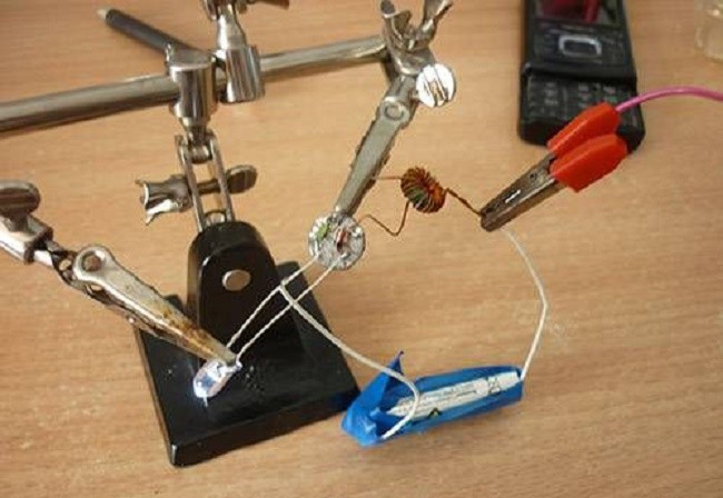
 I made myself such a simple device - charging from a mobile phone with crocodiles instead of a plug. Very convenient for turning on cell phones without a battery, recharging batteries instead of a “frog”, and so on. It's also good for checking LEDs.
For an LED, the polarity of the voltage is important; if you confuse the plus with the minus, the diode will not light up. This is not a problem; the polarity of each LED is usually indicated on the tape; if not, then you need to try both ways. The diode will not deteriorate from mixed up pluses or minuses.


LED lamp
For a flashlight it is necessary to make a light-emitting unit, a lamp. Actually, you need to dismantle the LEDs from the strip and group them according to your taste and color, according to quantity, brightness and supply voltage.
To remove it from the tape, I used a craft knife, carefully cutting off the LEDs directly with pieces of the conductive wires of the tape. I tried to solder it, but somehow I wasn’t able to do it well. Having picked about 30-40 pieces, I stopped; there was more than enough for a flashlight and other crafts.

LEDs should be connected according to simple rule: 4 volts for 1 or more parallel diodes. That is, if the assembly will be powered from a source of no more than 5 volts, no matter how many LEDs there are, they must be soldered in parallel. If you plan to power the assembly from 12 volts, you need to group 3 consecutive segments with an equal number of diodes in each. Here is an example of an assembly that I soldered from 24 LEDs, dividing them into 3 consecutive sections of 8 pieces. It is designed for 12 volts.
 Each of the three sections of this element is designed for a voltage of about 4 volts. The sections are connected in series, so the entire assembly is powered by 12 volts.
Someone writes that LEDs should not be connected in parallel without an individual limiting resistor. Maybe this is correct, but I don’t focus on such trifles. For a long service life, in my opinion, it is more important to select a current-limiting resistor for the entire element and it should be selected not by measuring the current, but by feeling the operating LEDs for heating. But more on that later.
I decided to make a flashlight powered by 3 nickel-cadmium cells from a used screwdriver battery. The voltage of each element is 1.2 volts, therefore 3 elements connected in series give 3.6 volts. We will focus on this tension.
Having connected 3 battery cells to 8 parallel diodes, I measured the current - about 180 milliamps. It was decided to make a light-emitting element from 8 LEDs; it will fit well into the reflector of a halogen spotlight.
As a base, I took a piece of foil fiberglass about 1cmX1cm, it will fit 8 LEDs in two rows. I cut 2 separating strips in the foil - the middle contact will be “-”, the two extreme ones will be “+”.

For soldering such small parts, my 15-watt soldering iron is too much, or rather the tip is too large. You can make a tip for soldering SMD components from a piece of 2.5mm electrical wire. To ensure the new tip stays in the large hole in the heater, you can bend the wire in half or add additional pieces of wire into the large hole.


The base is tinned with solder and rosin and the LEDs are soldered in observing polarity. The cathodes (“-”) are soldered to the middle strip, and the anodes (“+”) are soldered to the outer strips. The connecting wires are soldered, the outer strips are connected with a jumper.


You need to check the soldered structure by connecting it to a 3.5-4 volt source or through a resistor to a phone charger. Don't forget about the switching polarity. All that remains is to come up with a reflector for the flashlight; I took a reflector from a halogen lamp. The light element must be securely fixed in the reflector, for example with glue.

Unfortunately, the photo cannot convey the brightness of the glow of the assembled structure, but I will say for myself: the dazzle is not bad at all!

Battery
To power the flashlight, I decided to use battery cells from a “dead” screwdriver battery. I took all 10 elements out of the case. The screwdriver ran on this battery for 5-10 minutes and died, according to my version, the elements of this battery may well be suitable for operating the flashlight. After all, a flashlight requires much lower currents than a screwdriver.
 I immediately unhooked three elements from the common connection, they will just produce a voltage of 3.6 volts.
I measured the voltage on each element separately - all of them were about 1.1 V, only one showed 0. Apparently this is a faulty can, it’s in the trash. The rest will still serve. For mine LED assembly Three cans will be enough.
After scouring the Internet, I came to the conclusion important information about nickel-cadmium batteries: the nominal voltage of each element is 1.2 volts, the bank should be charged to a voltage of 1.4 volts (voltage on the bank without load), discharged should not be lower than 0.9 volts - if several cells are composed in series, then not lower than 1 volt per element. You can charge with a current of a tenth of the capacity (in my case 1.2A/h = 0.12A), but in fact it can be higher (the screwdriver charges for no more than an hour, which means the charging current is at least 1.2A). For training/recovery, it is useful to discharge the battery to 1 V with some load and charge it again several times. At the same time, estimate the approximate operating time of the flashlight.
So, for three elements connected in series, the parameters are as follows: charging voltage 1.4X3 = 4.2 volts, nominal voltage 1.2X3 = 3.6 volts, charging current - what will a mobile charger with a stabilizer made by me give.
The only unclear point is how to measure the minimum voltage on discharged batteries. Before connecting my lamp, the voltage on the three elements was 3.5 volts, when connected it was 2.8 volts, the voltage quickly restored when disconnected again to 3.5 volts. I decided this: with a load the voltage should not fall below 2.7 volts (0.9 V per element), without a load it is desirable that it be 3 volts (1 V per element). However, it will take a long time to discharge; the longer you discharge, the more stable the voltage will be, and it will stop dropping quickly when the LEDs are lit!

I discharged my already discharged batteries for several hours, sometimes turning off the lamp for a few minutes. The result was 2.71 V with the lamp connected and 3.45 V without load; I did not dare to discharge further. I note that the LEDs continued to shine, albeit dimly.
Charger for nickel-cadmium batteries
Now you need to build a charger for the flashlight. The main requirement is that the output voltage should not exceed 4.2 V.
If you plan to power the charger from any source of more than 6 volts - relevant simple circuit on KR142EN12A, this is a very common microcircuit for regulated, stabilized power supply. Foreign analogue of LM317. Here is a diagram of the charger on this chip:

But this scheme did not fit into my idea - versatility and maximum convenience for charging. After all, for this device you will need to make a transformer with a rectifier or use a ready-made power supply. I decided to make it possible to charge batteries from a mobile phone charger and USB port and a computer. To implement it, you will need a more complicated circuit:

The field-effect transistor for this circuit can be taken from a faulty motherboard and other computer peripherals; I cut it off an old video card. There are plenty of such transistors on the motherboard near the processor and not only. To be sure of your choice, you need to enter the transistor number into the search and make sure from the datasheets that it is a field effect one with an N-channel.
I took the TL431 microcircuit as a zener diode; it is found in almost every mobile charger or other pulse blocks nutrition. The pins of this microcircuit must be connected as in the figure:

I assembled the circuit on a piece of PCB and provided a USB socket for connection. In addition to the circuit, I soldered one LED near the socket to indicate charging (that voltage is being supplied to the USB port).


A few explanations about the diagram Because charging circuit will always be connected to the battery, the VD2 diode is necessary so that the battery does not discharge through the stabilizer elements. By selecting R4, you need to achieve a voltage of 4.4 V at the specified test point, you need to measure it with the battery disconnected, 0.2 volts is the reserve for drawdown. And in general, 4.4 V does not exceed the recommended voltage for three battery cells.
The charger circuit can be significantly simplified, but you will only have to charge from a 5 V source (the computer’s USB port meets this requirement) if phone charger produces more voltage - it cannot be used. According to a simplified scheme, theoretically, batteries can be recharged; in practice, this is how batteries are charged in many factory products.

LED current limitation
To prevent overheating of the LEDs, and at the same time reduce the current consumption from the battery, you need to select a current-limiting resistor. I selected it without any instruments, assessing the heating by touch and controlling the brightness of the glow by eye. The selection must be made on a charged battery; the optimal value between heating and brightness must be found. I got a 5.1 Ohm resistor.

Working hours
I performed several charges and discharges and got the following results: charging time - 7-8 hours, with the lamp continuously turned on, the battery discharges to 2.7 V in about 5 hours. However, when turned off for a few minutes, the battery regains its charge a little and can work for another half hour, and so on several times. This means that the flashlight will work for a long time if the light is not on all the time, but in practice this is the case. Even if you use it practically without turning it off, it should be enough for a couple of nights.
Of course, a longer operating time without interruption was expected, but do not forget that the batteries were taken from a “dead” screwdriver battery.
Flashlight housing
The resulting device needs to be placed somewhere, to make some kind of convenient case.

I wanted to place the batteries with LED flashlight in a polypropylene water pipe, but the cans did not fit even into a 32 mm pipe, because the internal diameter of the pipe is much smaller. In the end, I settled on couplings for 32 mm polypropylene. I took 4 couplings and 1 plug and glued them together with glue.

By gluing everything into one structure, we got a very massive lantern, about 4 cm in diameter. If you use any other pipe, you can significantly reduce the size of the lantern.

Having wrapped the whole thing with electrical tape for best view, we received this lantern:


Afterword
In conclusion, I would like to say a few words about the resulting review. Not every USB port on a computer can charge this flashlight, it all depends on its load capacity, 0.5 A should be enough. For comparison: Cell Phones When connected to some computers, they may show charging, but in reality there is no charging. In other words, if the computer charges the phone, then the flashlight will also charge.
Scheme for field effect transistor can be used to charge 1 or 2 battery cells from USB, you just need to adjust the voltage accordingly.
