Making a PC case. System unit made of wood. ASUS P5N-D motherboard specification
At first I didn’t want to write an article, I thought it was too simple, then I saw it and changed my mind.
Perhaps those who have a Raspberry Pi, some kind of Mini-ITX or other mini computer have thought about a case for it. Some people order online, others use a shoebox, but I suggest making it yourself.
On the knee from what we have.
By the way, I apologize in advance for the quality of the photos, I only had my phone at hand. And only when the case was completely assembled did it become possible to take a photo with a normal digital camera.
Tools and material
For my Mini-ITX, I decided to assemble a case from an old computer case, bought second-hand for 100 rubles. We will also need pliers, a hacksaw, various rasps, chisels, a hammer, a drill, electrical tape, super glue, screws, some rubber stuff, a screwdriver, a cutter, a can of paint, rags, alcohol, straight (but bending in the right places ) hands, pencil, ruler and cool music to feel like Tony Stark.
Possible options
Instead of a computer case, you can use a VCR case (it is usually thinner, which means it’s easier to process), a receiver case, a set-top box, some kind of toy, or just sheets of iron/plastic. Although I wouldn’t recommend plastic - it’s too… warming. Although you can always make holes for ventilation.Manufacturing
First, let's decide on the form factor. I decided to make it based on the principle of a box with a lid. It's simple, fast and doesn't require any special skills.Since the computer case is shaped like the letter “P,” it is necessary to cut it into separate sheets to make it easier to work with them in the future. Actually, you don’t have to saw it, but hollow it out, break it off, bend it until it breaks, and finally grind it down to holes using a grinding wheel with a motor (well, I don’t know what this thing is called, I actually have a grinding wheel with a 220V motor ).

Let's start making a box. We just attach our device and trace it with a pencil. It's that simple. Accuracy be damned, the tools still don’t allow you to be more precise. Of course, it’s not good to do this, so you can apply the markings in any way convenient for you. By the way, here's my hardware: 
The markings must be applied so that after placing the piece of iron inside, there is at least 5mm of space left up to the lid and on the sides. You don’t have to worry about the holes for the periphery for now - if you make them before bending, then when bending the wall may not bend evenly. Therefore, it is better to make holes when the box is almost ready.
After marking, you can begin sawing. Back in school I was taught that “the markings are not cut off, they always remain on the part.” The excess can then be trimmed with a file (although I did file it down). 
almost sawn part
So we cut out this square. Now it's time to saw off his ears. It’s easier to show than to tell: 
Further - more interesting. If we now begin to bend the edges, they will bend like a wave (not at a right angle, but in an arc). To solve this problem, I first tapped the line with a chisel at the bend. You could probably use something like a large vice, but I didn’t have that (there were small vices - but they were small... something like that). 
We bend the part and get a box. To prevent the “ears” from coming apart, I glued them with super glue. Believe me, it holds. Holds up well. When I screwed up and glued it crookedly, I tore it off only with a hammer, chisel and pliers. In the future, super glue was my faithful assistant. 
Now we need holes for the periphery. Using a ruler and pencil, mark the location for the holes on the front wall. Here you need to tell how the board will be attached to the bottom of the box. To prevent it from lying flat, I cut out legs for the motherboard…
... and glued them to the bottom of the box with super glue! Then I unscrewed the scarf, took measurements for the periphery and began cutting out the holes. First, we drill holes in the corners, then use a hacksaw blade to make cuts (cuts?) between the holes. Here the rags with which I wrapped the canvas came in handy. 
In general, you can finish with the bottom of the box. We grind down all the irregularities with a not rough (gentle? :)) file. By the way, remember what I said about rubber stuff? I don’t know what it is, it looks like some kind of plugs. I found them in a bag with screws from my computer case. By the way, there I found a beautiful mesh grid, which I later soldered to the cover above the board’s radiators. So these elastic bands can be used as legs. First, cut out circles from electrical tape to fit the rubber bands and glue them to the bottom of the box. After painting, you can tear them off and glue rubber bands in their place (yes, with the same super glue). 
Next we proceed to making the lid. It is made in exactly the same way as the bottom of the box. I only bent the walls with pliers, it didn’t turn out very neatly, but I didn’t have to worry about using a chisel. The hole for the grille is cut in the same way as for the periphery. When everything is ready, all the parts need to be wiped with alcohol or, more simply put, degreased. Regarding the drawing on the lid. I just found a picture of a dragon on Google, printed it out and cut it out. Next, I pasted several strips of electrical tape onto the lid: 
Then he attached the dragon and carefully traced all its contours with a cutter. After that, I removed the remaining paper and tape, and it turned out something like this: 
Yes, by the way, the grille! I just soldered it (just don’t laugh): 
When everything is ready, it's time to start painting. I had a can of black spray paint to apply to plastic. A couple of sprays and wait for the parts to dry. 
After that, glue the legs, screw the board and close the lid. Ready! A few more final photos: 

Good afternoon, Khabrovsk residents. Thank you very much for the invite! And although it’s not a good idea to start by translating other people’s posts, perhaps someone else will find this homemade project mega-cool.
This is a translation of a post from the Overclock.net forum. User Show4Pro decided to take out all the insides of his super computer and hang everything on the wall. Great idea perfectly executed. For those who are interested in how it was assembled and how it works - welcome to the cat.
The last time I updated my home machine was 1.5 years ago. Well, I thought about upgrading the car to i7 (before that there was Bloomfield), although in fact, more powerful processor I didn't need it. I wanted to buy a new case - Corsair 900D, to replace the 8 year old Super Armor. But I wanted something special, unique. In Battlestations on Reddit, I came across a very simple but elegant solution - a wall computer. And that's where the whole project began.
Accessories:
CPU: Intel Core i7 950
Motherboard: Asus Rampage III Extreme
Video cards: 2 x AMD HD7970
RAM: 6 x 2GB Corsair Dominator
SSD drives: 4 x 120GB Corsair Force GT SSD
HDD drives: 2 x 1TB WD Caviar Black
2TB WD Caviar Green
1.5TB WD Caviar Green
Power supply: Corsair AX1200i
Sound: Creative Sound Blaster Zx
Cooling:
Cooling for CPU:
CPU Water Cooling Radiator EK Supreme HF Full Copper
Pump Swiftech MCP655 /w Speed Control
The cooler itself FrozenQ Liquid Fusion V Series 400 ml Reservoir - Blood Red
XSPC RX360 Performance Triple 120mm Radiator
GPU cooling
Heatsink for video card EK FC7970 - Acetal+EN
The pump and cooler are the same as for the processor.
Swiftech MCP655/w Speed Control
FrozenQ Liquid Fusion V Series 400 ml Reservoir - Blood Red
Water cooling radiator Watercool MO-RA3 9x120 LT Radiator
Other:
Cooling system pipes
Koolance QD4 Quick Discounnect No-Spill Coupling
Bitspower G1/4 Silver Triple Rotary 90deg Compression Fittings
Monsoon Free Center Compression Fittings
Phobya Angled Clip 90° Tubing Guide
Phobya Terminal Strip Tubing Clip/Holder
The cooling tubes themselves (red) PrimoChill Advanced LRT Tubing Bloodshed Red
Phosphorizing refrigerant, blue color EK UV Blue Non-Conductive Fluid
Cables:
Bitfenix Alchemy Premium Sleeved Extensions
Corsair Individually Sleeved Modular Cables
Creation.
To start, I took photos of all the components in their actual sizes and put it all together in Photoshop. This way I was able to move them around the work surface and decide what it would look like. Well, this is also necessary for routing the cooling pipes. Here are a couple of layouts:
I abandoned this because of the empty space in the lower right corner. And the motherboard ended up on the left, although it should be in the very center and attract attention to the entire panel. 
There is also a lot of space on the right, although the power supply and motherboard are closer to the center. IN final version cooling tubes stretch along the entire right edge, plus two thermometers appeared there.

I transfer the drawing of the motherboard onto an acrylic sheet.

Since the video adapters will be far from the motherboard, I ordered PCIe slot extenders for each card on eBay. This is me testing how they work. However, later I had huge problems with the cross-function of the cards due to cheap unshielded wires. They ended up on top of each other and created serious interference. The system was stuck loading the BIOS. It was possible to launch it with only one card. In the end, I had to shell out for very expensive cables with good protection. But more on that later.

The goods have arrived!

Most of the water cooling is from Performance-PC. They even gave me a T-shirt and two mouse pads!

Acrylic backing for motherboard.

All acrylic panels are cut at 45° to achieve a glowing edge effect.

The holes are drilled and the fasteners are installed.
TA-dah!!! It turns out that the mother of Rampage III Extreme is eATX format. And this is for the ATX form factor.
I made the correct eATX substrate later.

Time to gut my old dusty case.


In the old computer, the disks are inserted into Vantec HDCS boxes, which make 3 HDD boxes out of 2 5.25" ones.


Video cards.

Supports for all components.

Custom acrylic pump mounts.

Close-up of rough trim done with a table saw. They will need to be sanded later.

There is a triangular cut in the center of each plate. It will reflect light that is projected perpendicularly inside the plate at the edges. Without a cut, the edges barely glow.


Test with the light on on the sound panel.

All panels are sanded with 120 grit wet sandpaper.

Close-up of sanding.
All back panels are pre-drilled.
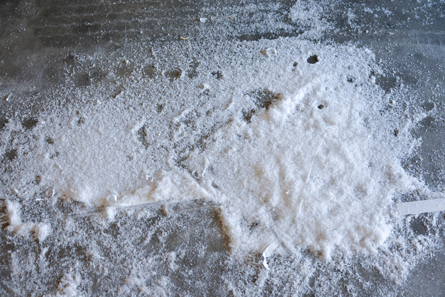
Under the table is acrylic snow.

Preparing to paint red.
Surprisingly, Corsair included thermal pads on the blades, although they don't get hot at all.

Marking all components on the main board to mark various slots and holes. Board - 1/4" 48 x 30 fiberboard.

All cracks and holes are marked in their places.

I'm getting ready to cut out the slots with a jigsaw.


I glue the frame.


I paint the inner edges black - to match the color of the carbon film.


Soldering LED strips.

Workplace.


LED strips. Temporary fastening.

I glue a giant vinyl film. This was the cruelest part. I almost had a heart attack. How to stick a film on a phone screen, only x1000 more.

No bubbles!


I use aluminum tape to hide the LEDs on the front side of the hard drive panel, between them.

My assistant is Tommy.

All substrates are installed in their places on the common board using #10 screws. I screwed them into pre-prepared holes.


Checking the light.

Coolant and cables have arrived. I used Bitfenix for the components and Corsair for the power supply.


On the left is Bitfenix, on the right is Corsair. Bitfenix doesn't have black heat shrink on the ends, so the Corsair looks cooler.

Red zip ties to tie up hanging wires.

Backside. All cables are connected.

We test for leaks while the entire system is lying on the floor - this makes it easier to troubleshoot problems.
First start.
Not loaded. I connected via iROG USB to the laptop to view the download log. It turned out that the system was stuck on the VGA BIOS. I disabled one of the video cards - everything worked. I tried to connect another one - it also works. Both cards are not. Did some research and found that unshielded PCIe extenders with ribbon cables are very susceptible to EMI. I tried to shield them by wrapping them in several layers of aluminum foil. 

After 4 layers of foil I was able to get both cards running. But the machine immediately froze as soon as I launched any game or any 3D editor. Moreover, my Soundblaster is also cascaded with a cable to the 3 x1 PCIe slot, and this also greatly interfered with the operation of the video and hung up the system.
As a result, with pain in my heart, I had to order expensive protected extenders for PCIe slots from 3M (approx. $100 each)

Shielded 3M extension cords in place. They turned out to be longer than the previous ones and now both video cards have reached PCIe x16.


Changed the previous sound to SoundBlaster Zx. This one looks amazing!

And finally
On this moment everything works smoothly. The installation has only 2 fans. It barely moves on the PSU, and I installed another one on the chipset - it’s very quiet. The pump runs at the lowest power, so the computer came out quite quiet. The only annoying thing is that it turns out that some components can be heard operating outside the case. In my case, this is the buzzing of the video and 1TV hard drive.EK UV refrigerant is very sensitive to ultraviolet radiation. I know you shouldn't mix coolants to preserve their properties, but damn if I used it undiluted, I wouldn't be able to see the coils in the reservoir. For both circuits I used about 1/8 of the jar, the rest was distilled water.
From the translator
I in no way claim any authorship of this incredible project. It’s just that I’m a journalist with a degree in electronics engineering, and doing such things is my dream. And to be honest, I would make a table, not a wall. So I decided, suddenly not all Khabrovsk residents are sitting on
Hello everybody!
It so happened that the case of my laptop (HP pavilion g7 2330 sr) did not stand the test of time, a corner broke off,
where the cover bracket with the display is attached, and attempts to find a new one at an adequate price were unsuccessful.
There are no whole used cases either, because this corner breaks for everyone. As a result, it was decided to turn the laptop into a desktop PC.
I immediately threw out the laptop case. DVD drive, battery, display and keyboard put up for sale. Eventually
What's left of the laptop: motherboard, hard drive HDD drive And wifi antenna. To cheer you up a little
original components, took another 120GB SSD for the system. To connect the HDD to the connector DVD drive,
I ordered a small adapter from Ali.
Since I work with wood at work, I decided to make the body from plywood. Drawings were made in CorelDraw,
because I cut plywood on a laser machine.

The dimensions of the case were 33x27x11cm. I made the case more thick, then I want to install another cooler or completely replace the original cooling system. The body itself was cut from 6mm thick plywood, and the decorative elements were made from 4mm plywood. All parts required two sheets of plywood approximately 50x50cm, and the total length of the cut was almost 42 meters.

The body was glued together with Moment wood glue.


I fastened the board to the case with bolts, so as not to cut holes in the case, cut out small washers from wood and pressed nuts into them.

To also be attached to the housing wall hard disks, cut out parts from acrylic. After trying on the board
and disks, glued washers and nuts to the wall of the housing.


I didn’t bother with the power button, it has a short cable, so I screwed it to the wall of the case under motherboard, and drilled a hole in the wall.

I cut the Wi-Fi antenna to fit the size of the top wall and glued it with double-sided tape.

The power connector in the laptop was on the other side of all the other connectors, I wanted all the connectors to be on one side, so the power cord had to be extended.

On the other side there is one more USB port, I decided to leave it inside the case; I will connect a bluetooth receiver for the keyboard and mouse to it.

Next we had to work hard with adjusting the holes for the connectors. A few test cardboard stencils and we were ready to cut out the remaining walls. I also cut it out on a laser machine from 2mm thick plastic for engraving, and I did the engraving for beauty.
Introduction
Modding (Englishmodding, comes from the word modify - modify, change) - introductioncreativechanges inHardwarecomputer.
By at least Wikipedia says so, but for those “avid” desktop computer users who have at least once tried to make changes to “their brainchild,” modding has become something much more than just “changing the appearance.” Actually, first you should try to find out the reasons why a modest user decides to make changes himself. In the archive of our website there are two extremely interesting articles: “Homemade cooling system for Radeon HD 4850” and “Modding the case to improve ventilation and reduce noise.” In both cases, the goal was the same: “to create efficient and quiet air cooling without significant investment,” and it is quite difficult to challenge it. After all, there are often cases today when users simply cannot choose a case that suits them, for example, since its filling is already in stock and has been in use for more than one month, but due to the insufficient (and often incorrect) ventilation system of the “old” case this filling heats up to extreme temperatures, and the standard cooling systems for the hottest elements (processor, video card) begin to work at full capacity. As a result, this leads to the fact that a seemingly far from cheap system unit turns into a real “vacuum cleaner” with the corresponding roar of turbines. Opening the side cover of the case, although it saves the contents from overheating, however, reduces the entire aesthetic appearance to “NO,” not to mention the fact that a working case in this form is a source of injury and increases the chances of losing expensive components due to careless movement or the pranks of a young child .
Purchasing a dedicated case, such as the Packard Bell ipower GZ-FA1CA-ASS, can make the difference this problem, but it’s not always possible to choose exactly what you want from what’s offered in the store, and to be honest, specialized cases are far from cheap and often their cost exceeds the price of the processor or video card. Not everyone can afford such waste. It is thanks to the combination of the above factors that modding cases are born, which are simply a modification and/or modernization of existing cases with a designed ventilation system. In addition, in this case, the author of such a manufactory body can, without hesitation, give his brainchild a creative, in his opinion, appearance, which often amazes others with its individuality and uniqueness. Vivid examples are the following creations, selected on the specialized Internet resource http://www.casemods.ru/:

The purpose of this article is to show, in the form of a chronological story of one case, that modding computer hardware is not something “abstruse”, accessible only to certified technical engineers, and to use examples to prove its promise, accessibility and, of course, simplicity. Readers will be able to find solutions to problems that have faced them in the past. Moreover, all changes presented will be accompanied by appropriate tests to assess changes in heating, performance and, indirectly, noise levels. If possible, the funds spent on modernization will be indicated and where the corresponding components can be purchased in different cities. Moreover, those who wish to take up the modding craft themselves will even be provided with drawings, on the basis of which, without much effort, it will be possible to design and create their own, exclusive, designed specifically for a specific computer configuration, a case with a set of necessary functions, or repeat what was proposed.
Background
The list of components that will take part in the presented mod project was not formed immediately, but evolutionarily over the course of four years. Initially (2004), the system unit had the following filling:

- Intel Pentium 4 540j processor;
- motherboard Intel D915PCY;
- ASUS EAX600XT video card;
- one DDR2 memory stick with a capacity of 1024 MB, operating at an effective clock frequency of 533 MHz.
However, then the plan was to buy not so much a desktop computer as a whole complex of consumer electronics based on personal computer, therefore, the system unit additionally included: CD-ROM Sony CDU5261; DVD-RW Sony D22A; FLOPPY Sony MPF920-Z/CU1; HDD Seagate ST3200822AS; TV-TUNER AverMedia 305; SOUND CARD Creative Audigy 2 ZS. The case itself was 3R System - Neon Light PRE. Monitor and kit acoustic speakers were corresponding: LG 920P and Creative Inspire TD 7700.

After the purchase, the question was increasingly raised: “Was this multimedia complex worth the crazy expenses spent on its acquisition, maybe something was chosen incorrectly?” The performance of the video adapter was naturally not enough, since a professional-level monitor could operate at a resolution of 1600*1200 with a screen refresh rate of 85 Hz, and popular games at that time (for example, DOOM 3) made quite serious demands on the contents of the system unit (especially the video card) even by modern standards. The dream of “the very best” was melting before our eyes. Over time, I read a lot of reviews of computer components and, unfortunately, not very carefully. In 2007, an upgrade was made (replacing some components with more efficient ones).

The video adapter was replaced by the extremely promising (just launched on sale) ASUS EN8800GTS/HTDP/512M, which was nothing more than a “reference” PNY GeForce 8800 GTS 512, only with ASUS stickers. Due to increased requirements for system power consumption, the 300-watt Dinamic ATX 1.3 power supply supplied with the case was replaced with PowerLux PL-550PFC-DF. Alas, 2007 marked a massive transition from single-core to dual-core processors. Naturally, most games were originally developed for dual-core processors, and the Intel Pentium 4 540j used in the system was simply not capable of providing the required level of performance. Even the add-on didn't help random access memory up to 3 GB with another stick with a capacity of 1024 MB and two 512 MB. The situation looked exactly like this: “the money was spent extremely illiterately.” Since the spring of 2008, probably more out of necessity than “optional,” we have been extremely meticulously re-reading all the articles and reviews on the relevant sites. It was at that time that I first got to know the website www.EasyCOM.com.ua, which amazed me with its scale and number of reviews. Each motherboard, video card, processor and other components that were on sale were described in detail, as if it were an exclusive and unique “new product”. Comparative dynamic testing of processors and video cards with similar models, regardless of class, generation or price range, was especially useful. By the summer of 2008, a decision was made, without haste, to systematically create an extremely non-standard system that would not cost a lot of money, assuming the use of the maximum number of currently available components, but would have such computing power that would meet modern requirements and have “reserve for the future” . The orientation of such a system was purely for games, watching video content and listening to audio. The only rational solution to this problem was to create an SLI system based on a specialized motherboard and a quad-core processor. That is, in order to increase the computing power of the video system, it was decided not to change the video card, but to supplement the computer with another one of the same type (based on the principle of organizing SLI systems). Since at that time there was no need to have special funds, and the time of popularity of the GeForce 8800GTS 512 was coming to an end, and there was no point in waiting, since within six months the ASUS EN8800GTS/HTDP/512M could not be found on sale, it was decided First of all, buy a second video card without having the appropriate motherboard. By the beginning of 2009, an Intel Core 2 Quad Q9550 processor and two OCZ Titanium OCZ2T800IO1G RAM sticks had already been purchased; all that remained was to choose a motherboard. As it turned out, at that time the raging financial crisis had completely swept away all new products from store shelves, and choosing an SLI-compatible motherboard (which were already a rarity) became an extremely difficult task. By and large, the choice was only between ASUS P5N-T Deluxe and ASUS P5N-D. Naturally, ASUS P5N-T Deluxe had an order of magnitude better opportunities than the second option. Take, for example, the processor power system, because it will be the quad-core Intel Core 2 Quad Q9550, famous for its high power consumption and heating, that will be used. However, the case decided itself. While the decision was being made, the ASUS P5N-T Deluxe motherboard simply disappeared from stores. There is only one variant left, ASUS P5N-D.


Because the motherboard ASUS P5N-D was produced by the manufacturer in rather limited quantities, it was not tested in a timely manner, so I would like to tell you about it in a few words now. It is based on a combination of system logic NVIDIA nForce 750i SPP + NVIDIA nForce 750i MCP + NVIDIA nForce 200. The board is compatible with all processors for Socket LGA 775, including quad-core models on the Yorkfield core, made according to 45 nm technical standards. The motherboard has two PCI-E x16 v2.0 slots, which are capable of working simultaneously in full x16 + x16 mode. The latter, in fact, is the “highlight” of this board, since the NVIDIA nForce 750i SPP northbridge has only 16 PCIe lanes, and to support full-speed two PCI-E x16 v2.0 ports, 32 are needed. So, an additional NVIDIA nForce 200 chip is capable of expanding the number of PCIe lanes and speeding up the transfer of information between video cards, without transmitting it through the chipset and processor, but directly directing it to its destination. More detailed information You can learn about the NVIDIA nForce 750i SLI system logic set by looking at the following diagram:

The board also has two PCI v2.2 slots, one PCI-E x1, four DIMM slots supporting DDR2 memory with frequencies of 800/677/533 MHz. A set of ports on the board for peripheral devices I/O includes one IDE for two devices, one Floppy connector, four SATA ports, two USB headers for four ports, one IEEE 1394a port, and an S/PDIF output connector. The board has a 24-pin power connector and a four-pin ATX12V connector for additional processor power. In the corner there are pads for connecting the front panel, headphones, and microphone. The interface panel displays four USB ports, one IEEE 1394a, six audio codec inputs/outputs, one optical audio output, one coaxial audio output, network LAN (RJ45), two PS/2 for connecting a mouse and keyboard, as well as one serial and parallel port. The number of connected fans to the motherboard is limited to four, including a four-pin processor fan.

ASUS engineers approached the arrangement of elements of the P5N-D motherboard quite boldly. Despite the fact that the ATX standard requires up to seven expansion slots on the motherboard, in the case of the ASUS P5N-D only six were implemented, thereby increasing the distance from the processor socket to the first expansion slot by 22 mm. This was quite enough for the location of the NVIDIA nForce 750i SPP north bridge chips and the so-called NVIDIA nForce 200 “east bridge”. Given their heat dissipation, they were covered with a massive heatsink.

For more efficient heat removal, a fan was supplied with the motherboard.

The dimensions of this “dwarf” are 70x70x10 mm. (D.Sh.V.), and the rotation speed of the impeller when powered by 12 V is 3800 rpm. In practice this is quite a noisy 'creation', however the BOIS options allow the latter to be used in three modes that correspond to the 3800; 3000; 2600 rpm
More detailed information about the configuration and characteristics can be gleaned from the corresponding table, or from the official website:
Specification of mother ASUS boards P5N-D:
|
Manufacturer |
|
|
NVIDIA nForce 750i SLI |
|
|
CPU socket |
|
|
Supported processors |
Intel Core 2 Quad / Core 2 Extreme / Core 2 Duo / Pentium Extreme / Pentium D / Pentium 4 |
|
System bus, MHz |
1333 /1066 / 800 / 667 MHz |
|
Memory used |
DDR2 800/667/533 MHz |
|
Memory support |
4 x 240-pin DIMMs, dual-channel architecture up to 8 GB |
|
Expansion slots |
2 x PCI-E x16 s NVIDIA support SLI |
|
Scalable Link Interface (SLI™) |
Supports two identical NVIDIA SLI-Ready video cards in x16 mode |
|
Disk subsystem |
The nForce 550 SLI Southbridge supports: |
|
VIA VT6038P controller |
|
|
Marvell 88E1116 Gigabit LAN Controller with AI NET 2 Support |
|
|
24-pin ATX power connector |
|
|
Cooling |
A massive radiator for cooling the NVIDIA nForce 750i SLI north bridge and the NVIDIA nForce 200 PCI-E expansion chip with a complete fan, as well as a proprietary radiator for cooling the NVIDIA nForce 570 SLI south bridge |
|
Fan connectors |
1 x CPU |
|
External I/O ports |
2 x PS/2 port for connecting keyboard and mouse |
|
Internal I/O ports |
4 x USB |
|
8 Mb Flash ROM, Award BIOS, PnP, DMI2.0, WfM2.0, SM BIOS 2.3, Multi-language BIOS |
|
|
Overclocking options |
Frequency change: FSB, PCI-Express, memory. |
|
Proprietary technologies |
ASUS EPU (Energy Processing Unit) |
|
Equipment |
Instructions and user guide |
|
Form factor Dimensions, mm |
ATX 12"x 9.6" |
|
Products webpage |

It’s worth spending a few words on the processor power system. It is made according to a four-phase scheme, but it should be understood that “the phases are different.” Here, for example, is what similar power systems look like:

The photo on the left shows the ASUS P5Q SE motherboard, which also has a four-phase power system, but it should be noted that the number of power transistors in the arm of one phase is two. The GIGABYTE GA-EP41-UD3L motherboard (in the middle of the photo) again has a four-phase power system, but the number of power transistors on the shoulder is no longer two, but three. Well, the GIGABYTE GA-EP45-UD3 motherboard located in the photo on the right has a six-phase power system, but, as in the previous case, the number of power transistors on the shoulder is three. The fact is that the number of power transistors in one “phase” and the total number of phases in the processor power system is directly proportional to the maximum power that this power system can “produce.” And if the consumer (processor) consumes such power that borders on the maximum possible that the processor power system is able to provide, then the latter will, at best, become very hot, which will undoubtedly affect the service life of both the motherboard and the processor . ASUS engineers did something more cunning. Although the number of phases was limited to four, each arm was equipped with four power transistors, which indicates a predisposition to heavy loads. It is extremely difficult to more accurately evaluate the power supply system of the ASUS P5N-D motherboard, but it is assumed that it is designed for powerful quad-core processors with some reserve, and in fact, this reserve can, in theory, be implemented to ensure the increased power consumption of an overclocked quad-core processor. Practice will show how much overclocked it is.

There is also not much to talk about the functionality of the BIOS. Overclocking capabilities (which are mostly interesting) are limited to changing the frequency of the FSB reference bus from 133 to 750 MHz (although this parameter is presented not by the usual FSB, but by QDR, that is, FSB x 4), PCI-E bus from 100 MHz to 131 MHz, frequencies memory operation from 400 MHz to 2600 MHz, changing the HT bus multiplier connecting the north bridge and the south bridge, from x1 to x8, as well as changing the RAM timings, both main and additional. You can change the supply voltage on the following elements: processor from 0.83125 V to 1.6 V; RAM from 1.85 V to 3.11 V; Northbridge NVIDIA nForce 750i SPP from 1.2 V to 1.76 V; south bridge NVIDIA nForce 750i MCP from 1.5 V to 1.86 V; HT bus from 1.2 V to 1.96 V.
Summing up a quick review of the ASUS P5N-D motherboard, we can draw a brief but clear conclusion. This motherboard has everything you need to build a high-performance SLI system with a full connection of two video adapters using the x16 + x16 scheme and using the most powerful processors of the Intel Core 2 Quad family. However, despite almost flagship functions, ASUS P5N-D has “nothing extra”, that is, the number of additional expansion controllers is minimal, advanced ASUS technologies are not fully used, and the number of additional radiators is kept to a minimum. All this, naturally, affected the final cost of the product. The motherboard was purchased in February 2009 at a price of 1200 UAH, which, in comparison with the price of ASUS P5N-T Deluxe, which was estimated at 1800 UAH, looked extremely promising. As for the overclocking potential, there was no reliable information on the Internet at the time of purchase; one could only hope for “maybe.”
In principle, the system was already assembled, with the exception of the processor cooler. The situation with applicants for this “position” turned out to be more deplorable than with motherboards. And the budget allocated for updating the computer has simply dried up. The following solution was purchased.


Unlike Thermaltake Cyclo 12cm Red Pattern, this model does not show various animated logos, but “writes” the Thermaltake logo, shows the approximate temperature of the air passing through the fan (there is a built-in temperature sensor), as well as the relative noise level created by the fan. In practice it looks like this:

It would be difficult to resist the temptation to see this “miracle” on the front panel of a home-made case. Despite the somewhat expensive purchase, we purchased three Thermaltake Cyclo 12cm Logo Fan Pattern fans and one Thermaltake Cyclo 12cm Red Pattern for variety. As you might guess, three of them will pump air into the upper part of the case, where the motherboard and video cards are located, as well as the processor cooler, and one in bottom part case, where there is only one element that needs airflow - the power supply.
The Thermaltake fans mounted on the front panel using wood screws looked like this:

When marking out the shelf for the motherboard under the mounting posts, I remembered a rather “acute” problem that many people have. This refers to the bending of the motherboard PCB due to the rigid fastening of the cooler without a pressure plate on the back side of the processor socket. The solution looked like a homemade analogue of a pressure plate. Having selected felt of the required thickness (about 7-8 mm), a square was cut out with dimensions slightly larger than the cooler mounting holes for the Socket LGA 775 processor socket.

Considering the height of the motherboard mounting stand was 6 mm, the felt was 1-2 mm higher, and it was this difference that provided the necessary rigidity when the motherboard PCB was deformed. You can buy felt either in specialized construction stores or “from hand” in spontaneous markets. The price of such a piece can be from 5 to 30 UAH.
The last stage of rough processing of the future case was the organization of the necessary holes in the motherboard shelf for mounting power wires and cables hard drives, disk drive, etc.

Having temporarily screwed the motherboard into place, the location and type of connectors were simply labeled with a marker. Then, with the help of an electric drill and a file, these technological holes appeared. Their dimensions were so small that the corresponding plugs could fit into them. Conventionally, the upper and lower parts of the case should be separated from each other almost hermetically to achieve more efficient air flow in the upper part of the case, where the hottest elements are located.
Having come close to giving the body an aesthetic appearance, the question became: “How, exactly?” After much thought and comparison of capital investments, the following two materials were considered the most profitable.

Elementary “self-adhesive”. An analogue of what is used to cover the walls of apartments during renovation, that is, wallpaper that has an adhesive substance applied on one side. This type of material is made from thick paper or a kind of rubberized oilcloth. The color scheme is limited purely by human imagination or the availability of assortment in the store: from pure white to photo wallpaper. This “happiness” is sold in rolls per linear meter. There are two types of rolls in width: 450 mm and 550 mm. The price varies depending on the complexity of the design and the width of the roll, ranging from 11 UAH to 22 UAH per linear meter. In our case, we chose a black “self-adhesive” with a shiny varnish effect. Moreover, it had a base with an extruded wood structure. Having carried out a simple calculation, it turned out that five meters of “self-adhesive” are needed to cover the entire future body.
The second material is called double-sided foam tape.

The purpose of its application was to use a seal at the points of contact of vibrating computer components (drives, hard drives) with the walls of the case, as well as between the walls of the case. The photo above shows that it was used to seal the “windows” of the front panel into which the drives will be installed. In terms of its consistency, foam rubber, from which strips 12-18 mm wide and 2 mm thick are made, is very soft and can be compressed up to 0.5 mm, while also springing. It was simply not possible to find a more suitable seal. The presence of an adhesive and viscous substance on both sides made it possible to firmly secure this seal, and in some cases even use it to secure computer components.
As a result, the disassembled appearance of the Birdhouse 001 case was as follows:

Compared to the original look of the chipboard, this interpretation still looked much better. Black lacquered wood mixed with chrome grilles and acrylic (transparent) fan covers looked solid. It was then that another “brilliant” element of the body was born, the lining on the ends of the side walls:

In fact, this is a “U” shaped profile for finishing the end edges of chipboard, which is quite widely used in the manufacture of furniture and can be made of plastic or aluminum. In our case, we used plastic, the color “chrome mirror”. Sold in slats 2.5 m long, at a price of 22-25 UAH per piece. Two such strips are enough to finish both side walls of the case.
So, there is only one step left before assembly begins - a “basket” for attaching hard drives, drives, a floppy drive and a card reader. The use of a standard “basket”, which is used in serial cases, is impossible due to the non-standard arrangement of the above devices. The solution turned out to be as simple as it was non-standard:

By pure chance, a modest piece of plexiglass 4 mm thick and measuring about a meter by meter turned out to be available. The appearance of this piece did not allow it to be used “in plain sight”, but for the original material of the “basket” there is simply no better option.

The cutting of this material was carried out using a manual angle grinder or a grinder. This procedure did not cause any particular difficulties and can be done by anyone with sufficient patience and caution. All that remained was to drill the necessary holes and that was it.

Although plexiglass has some elasticity, it simply crumbles if handled carelessly. In order to drill a hole in it with a diameter of 3.5 mm, it is necessary to do this in three or four passes, starting with a drill with a diameter of 1 mm and ending with 3.6 mm. Since I will use 3 x 8 mm bolts with a countersunk head to fasten the “basket” elements, it is necessary to create a kind of “socket” for the bolt head after drilling the hole. This is done with a drill of the same diameter as the cap. In our case 6 mm. As a result, the parts ready for assembly looked like this:

Since the case is planned to be as quiet as possible, the same sealant made of double-sided tape on a foam rubber base was used to secure the drives, disk drive and card reader.

Since the drives, disk drive and card reader are a structural part of the “basket”, their fastening must be rigid and durable.

As many have guessed, hard drives will generally have to be mounted in a 5.25" bay (for drives), and the hard drives themselves are 3.5" in size. A way out of this situation was found not only in terms of structural joining, but also in terms of sound insulation. Hard drives “tightly” screwed to the “basket” will transfer their vibration to the latter, and this is an extra source of noise. To eliminate it, we propose a simple and at the same time tricky way, for which you will need four erasers, which everyone at school or universities used to erase pencil graphite from a piece of paper.

The latter are sold in stationery stores in different shapes, colors and even scents at prices ranging from 50 kopecks to 4 UAH per piece. All that remains is to choose the right size and perform the following operations:

Cut into pieces of the required size, drill a hole lengthwise and screw in a 3 x 8 mm pin halfway on one side. The latter is obtained from the bolt that fastened the drives; you just need to bite off the head with pliers. When mounted with a hard drive it looks like this:

Then everything is simple, installing the upgraded HDD It is bolted into the 5.25" compartment, just like the drive. The uniqueness of the noise insulation is that there is no rigid fastening, and all vibrations will be absorbed by the same erasers.

Well, now everything is ready, it’s time to assemble the body. The installation of the lower part of the case, where the “basket” with drives, hard drives, floppy drive, card reader and power supply is located, looked like this:

As planned, the power supply was disassembled and switched to conditionally passive cooling mode. Although in fact it is cooled by a Thermaltake Cyclo 12cm Red Pattern fan, which pumps air into the entire lower compartment of the Birdhouse 001 case. There is simply nothing more to say about the lower part of the case; at this stage it is “tightly” closed and the work is transferred to the upper part of the case, where the motherboard is located.

Examining this photo carefully, experienced overclockers would probably object to the use of the Thermaltake Ruby Orb cooler, however, as was written at the beginning of the article, the choice on store shelves was extremely limited, as was the budget allocated for this computer. But these are not all the reasons why the decision was made, nevertheless, to use Thermaltake Ruby Orb. The massive heatsink on the motherboard hid two “hot” elements: the NVIDIA nForce 750i SLI north bridge and the NVIDIA nForce 200 expansion controller. In any case, this heatsink requires forced airflow, which the Thermaltake Ruby Orb processor cooler can handle perfectly. Well, the last thing that many may have already guessed is the dimensions. The height of the upper compartment of the case is equal to the height of the fans that will pump cool air, that is, 120 mm. A high-performance heatpipe cooler that would be lower than ~105 mm simply did not exist at the time the case was assembled, although a couple of months later Scythe Shuriken and Scythe Big Shuriken appeared on sale:

These coolers would likely be more efficient than the Thermaltake Ruby Orb solid aluminum heatsink.

Having installed all the components (two ASUS EN8800GTS/HTDP/512M video cards and sound card Creative Audigy 2 ZS), which were supposed to be used, the situation was quite interesting:


There was simply no vertical free space in the upper part of the Birdhouse 001 building. All components literally rested their heads on the ceiling. However, there was even a free area in the horizontal plane. This is exactly how it was intended. According to the author, such “crowding” will force the air pumped by three Thermaltake Cyclo 12cm Red Pattern fans to pass only through the cooler radiators, thereby ensuring maximum cooling efficiency. A similar technology is being used in powerful video adapters that require serious cooling.

To estimate the dimensions, the following photographs are attached, since the dimensions 290x400x400 mm (W.D.H.) cannot convey them clearly; for comparison, “boxed” versions were attached to the case licensed game S.T.A.L.K.E.R., which a good half of gamers will find:

Compared to most serial Middle Tower cases with dimensions on average of 450 x 250 x 450 (WHD), this case can even be perceived as a “thick” Desktop, especially in comparison with Full standard cases popular among overclockers and lovers of silence Tower, with an average size of 250 x 550 x 520 (W.D.H.).
Well, as they say, the final touch! Disproportionately large side walls, which also double as legs.


Well, actually, here it is – “Birdhouse 001”. Perhaps, for many, this form of the system unit will seem strange, but this is exactly how its author saw a quiet and productive, creative and stylish case. However, everyone has their own opinion - constructive criticism is welcome on the forum of our site.

Testing
Of course, you won’t be satisfied with just your appearance. The case should not only be pleasing to the eye, but also effectively cool the contents. Just to evaluate the effectiveness of the transition from the upgraded 3R System - Neon Light PRE case to the modding homemade “Birdhouse 001”, attached are the test results, which were carried out in two modes. The first one was conditionally “without acceleration”. All frequencies and voltages were set to AUTO mode, with the exception of the processor supply voltage, which is set to 1.25 V by default on the ASUS P5N-D motherboard for some unknown reason.

In practice, it was found that the processor remains completely stable when a supply voltage of 1.075 V is applied, which naturally affects its heating.

For forced maximum heating Intel processor The Core 2 Quad Q9550 used the LinX stress test program, and FurMark, which was similar in purpose, was used to heat up the video adapters. Also, as a control measurement of temperatures, the Futuremark 3DMark "06 test was performed, where in theory the motherboard chipset should have warmed up more. It should also be noted that for maximum adequacy of the results, a household air conditioner was used. The purpose of its use is banally simple: for a while testing to maintain the air temperature in the room at 24 ° C. Thermaltake Cyclo 12cm Red Pattern fans located on the front panel of the Birdhouse 001 case were used as additional sensors. However, although they have a price that is twice as high as similar fans (only without backlight) but the benefits from them more than cover the unnecessary costs.
|
System element |
Temperature, °C |
||
|
3R System - Neon Light PRE |
"Birdhouse 001" |
||
Analyzing the results, we can safely say that the modernization was not in vain. The processor temperature decreased by two degrees in idle mode, and by five degrees in stress testing mode. Video adapters are finally approaching a “sane” temperature range, which immediately affects the operation of their cooling systems. In games or other 3D loads, the turbines no longer worked at 100%, but were limited to a range of 40-70%, which was very pleasing to the ear.
The decrease in processor temperature made me think seriously about overclocking it, since there is potential for this. Using the already outlined settings, several attempts were made to pass stress testing at different frequencies. As a result, after comparing the frequency/heating ratio, it was decided to operate the system at the following frequencies:

The FSB bus operated at a reference frequency of 376 MHz, which, together with the x8.5 multiplier, made it possible for the processor to operate at a final clock frequency of 3200 MHz. At the same time, it was necessary to increase the supply voltage from 1.075 V to 1.15 V. All other supply voltages remained the minimum that could be set in the BIOS. As a result, the temperature of the main elements took the following values.
|
System element |
Temperature, °C |
||
|
3R System - Neon Light PRE |
|||
Since the system is positioned as a productive computer for games, it should be shown what kind of performance it shows this system directly in games. And at the same time, what kind of gain did the system get from increasing the processor clock frequency by 364 MHz.
|
Benchmark |
Settings |
3R System - Neon Light PRE |
Birdhouse 001 Intel Core 2 Quad Q9550@3200 |
|||||
|
Average FSP / result |
Average FSP / result |
|||||||
|
Standard |
||||||||
|
S.T.A.L.K.E.R. ClearSky Benchmark |
Maximum Improved Dynamic Lighting 1600 x 1200 |
|||||||
|
Sun rays |
||||||||
|
Crysis Warhead FBWH BenchTool |
1600 x 1200 AA-x0 |
|||||||
|
1600 x 1200 AA-x8 |
||||||||
|
RESIDENT EVIL 5 Benchmark Version |
1600 x 1200 AA-x0 |
|||||||
|
1600 x 1200 AA-x8 |
||||||||
|
1600 x 1200 AA-x0 |
||||||||
|
1600 x 1200 AA-x8 |
||||||||
|
1600 x 1200 AA-x0 |
||||||||
|
1600 x 1200 AA-x8 |
||||||||
|
1600 x 1200 AA-x0 |
||||||||
|
1600 x 1200 AA-x8 |
||||||||
|
1600 x 1200 AA-x0 |
||||||||
|
1600 x 1200 AA-x8 |
||||||||
|
X3 Terran Conflict Rolling Demo |
1600 x 1200 AA-x0 AF –x0 |
|||||||
|
1600 x 1200 AA-x8 AF –x16 |
||||||||
|
1600 x 1200 AA-x0 AF –x0 |
||||||||
|
1600 x 1200 AA-x8 AF –x16 |
||||||||
|
1600 x 1200 AA-x0 AF –x0 |
||||||||
|
1600 x 1200 AA-x8 AF –x16 |
||||||||
|
1600 x 1200 AA-x0 AF –x0 |
||||||||
|
1600 x 1200 AA-x8 AF –x16 |
||||||||
|
1600 x 1200 AA-x0 AF –x0 |
||||||||
|
1600 x 1200 AA-x8 AF –x16 |
||||||||
The average performance increase in test programs and games was approximately 5%, which is not as much as we would like. Most likely, the weaker point in the system is the unoverclocked video cards, and the situation will change little if the processor clock frequency is further increased. Of course, it is possible to overclock video cards; moreover, there have been attempts to take this action:

However, to ensure an acceptable temperature regime, it took half an hour to cool the temperature in the room to 17 °C using an air conditioner and continuously maintain it during testing. It makes no sense to talk about such exploitation on an ongoing basis.
Bottom line
Modding is a great way to improve technical characteristics computer. Depending on its direction, you can achieve a more comfortable acoustic mode of operation of the system unit or make its contents work faster, or perhaps both at once. Using the example of the case described in this article, it is clearly seen that there is nothing complicated in this process, and even in terms of capital investment, such global work in total did not exceed 500 UAH. If we limit ourselves to simple fans, and not animated ones, then the final investment will be only about 350 UAH. In any case, both amounts are significantly less than the price of specialized Middle Tower and, especially, Full Tower cases.
And of course, modding is a great way to create something of your own, personal and unique, creative and high-tech, reflecting the “true face of the creator and owner.” After all, it’s so nice to present your creation to the public during some celebration, which will always be appreciated by knowledgeable people, or post photos of it on the Internet, where it will always be appreciated.
Positive consequences of creating the Birdhouse 001 building:
- unusual stylish appearance that matches the interior of the room and furniture;
- high cooling productivity with small dimensions;
- significantly reduced noise level compared to the original housing;
- opportunity to increase clock speeds components without the risk of overheating;
- eliminating annoying vibrations from the operation of drives and hard drives.
Negative features of the Birdhouse 001 case:
- skills in working with a soldering iron, drill, grinder, emery, file and other tools are required, as well as their availability on the farm;
- the complexity of the production process, requiring a lot of free time and patience;
- additional capital investments were required;
- inaccessibility of the contents of the case after assembly.
Afterword
Few readers wondered about the durability of modding solutions and their “health.” I would like to leave a note in the afterword that the “Skvorechnik 001” building, without any comments, exactly in the form in which it is presented in the article and with the same acceleration worked for almost eight months, starting from the date of its creation - February 2009, and ending the date of his “retirement” is October 2009. You will find out what was the reason for sending such a seemingly competent corps “to retirement” in the second part of the material. You will also learn about the hidden overclocking potential of the components of this system, and you will actually see the new case, which is listed under the code name “ Birdhouse 002WaterWorld" In the meantime, as an announcement of a future review, the following photo is attached:

Article read 42247 times
| Subscribe to our channels | |||||
|
|
|
||||
A little background from the author about how and why he decided to do his own computer modding.
According to the author, his system was updated 1.5 years ago, and he decided to change the processor to a more powerful one, as well as change his old building Super Armor for the new Corsair 900D, and this seemed to be enough, but the author decided not to stop there, since he wanted something unusual and special; out of all the variety of options, he liked the idea of a wall-mounted computer. This is how this difficult project began.

Let's move on to the creation process.
The author began by taking photographs of all components in their actual size, and used Photoshop program, so he could move all the parts around the workspace and see what it might look like. There are several such examples in the photo. By distributing all the components, the author wanted to achieve maximum filling of the free space. In the final version, the cooling tubes will stretch along the entire right edge, and two additional thermometers will be placed.
Next, an acrylic sheet of plastic was taken, onto which the drawing of the motherboard was transferred. Since the video card will be located at a sufficient distance from the motherboard, I had to buy extension cables for the PCIe slot; it is recommended to buy more expensive cables, since they have more good protection, and they will not cause interference.
This is what some of the ordered components look like.
We cut all the panels at an angle of 45 degrees, this is necessary so that the glow at the edges is more effective.
Now it's time to tear up your old computer.
On the old computer, the hard drives were placed in special Vantec HDCS boxes; they make 3 HDD boxes out of 2 5.25" ones.
To properly reflect light, a triangular cut is made in the center of the plates; without it, the edges glow slightly.
All panels must be wet sanded sandpaper, with 120 grit.
When the markings are ready, we cut out special slots with an electric jigsaw.
Then the frame is glued.
The inside of the cutouts was painted black, specifically to match the color of the carbon sticker.
Now we move on to soldering the LED strips, temporarily fix them with electrical tape, and see what happens.
It's time to glue the vinyl film, be patient, as the process is very stressful.
Using aluminum tape, cover the LED backlight for hard drives.
After the coolant and the required number of wires have been received, we begin the connection. To prevent the wires from sagging, a tie was used.
Check the water cooling for leaks.
We are starting the system for the first time.
The first launch was unsuccessful, the system constantly hung, two video cards refused to work, the fault was with PCIe extenders with ribbon cables, which turned out to be very susceptible to electromagnetic interference. There was an attempt to make additional protection using foil, but this did not give much result.
The only thing that helped solve this problem was buying a very expensive cables who had the necessary protection.
A few final words.
The wall computer turned out to be quite quiet, the whole system works smoothly, the desired result has been achieved!
The author provides a photo report of the finished modding.
