Low frequency power amplifiers on tda7294. Subwoofer amplifier based on TDA7294 (bridge circuit). Amplifier block diagram
The TDA7294 microcircuit is an integrated low-frequency amplifier, which is very popular among electronics engineers, both beginners and professionals. The network is full different reviews about this microcircuit. I decided to build an amplifier on it. I took the diagram from the datasheet.
This “micruha” feeds on a bipolar diet. For beginners, I will explain that it is not enough to have a “plus” and a “minus”.
You need a source with a positive terminal, a negative terminal and a common one. For example, relative to the common wire there should be plus 30 Volts, and in the other arm minus 30 Volts.
The amplifier on the TDA7294 is quite powerful. The maximum rated power is 100 W, but this is with nonlinear distortion of 10% and at maximum voltage (depending on load resistance). You can reliably shoot at 70W. Thus, on my birthday, I listened to two parallel-connected “Radio Engineering S30” speakers on one TDA 7294 channel. The entire evening and half of the night, the speakers sounded, sometimes putting them into overdrive. But the amplifier withstood it calmly, although it sometimes overheated (due to poor cooling).
Main characteristicsTDA7294
Supply voltage +-10V…+-40V
Peak output current up to 10A
Operating temperature of the crystal up to 150 degrees Celsius
Output power at d=0.5%:
At +-35V and R=8Ohm 70W
At +-31V and R=6Ohm 70W
At +-27V and R=4Ohm 70W
With d=10% and increased voltage (see), you can achieve 100W, but it will be a dirty 100W.
Amplifier circuit for TDA7294
The diagram shown is taken from the passport, all denominations are preserved. With proper installation and correctly selected element values, the amplifier starts the first time and does not require any settings.
Amplifier elements
The values of all elements are indicated in the diagram. Resistor power 0.25 W.
The “microphone” itself should be installed on the radiator. If the radiator is in contact with other metal elements of the case, or the case itself is the radiator, then it is necessary to install a dielectric gasket between the radiator and the TDA7294 case.
The gasket can be silicone or mica.
The radiator area should be at least 500 sq.cm, the larger the better.
Initially, I assembled two channels of the amplifier, since the power supply allowed, but I didn’t choose the right housing and both channels simply did not fit into the housing in terms of dimensions. I tried to make the PCB smaller, but it didn't work.
After fully assembling the amplifier, I realized that the case was not enough to cool one channel of the amplifier. My case was a radiator. In short, I rolled out the lip into two channels.
When listening to my device at full volume, the crystal began to overheat, but I lowered the volume level and continued testing. As a result, I listened to music at a moderate volume until midnight, periodically causing the amplifier to overheat. The TDA7294 amplifier turned out to be very reliable.
ModeSTAND- BY TDA7294
If 3.5V or more is applied to the 9th leg, the microcircuit exits sleep mode; if less than 1.5V is applied, it will enter sleep mode.
In order to wake the device from sleep mode, you need to connect the 9th leg through a 22 kOhm resistor to the positive terminal (source bipolar power supply).
And if the 9th leg is connected through the same resistor to the GND terminal (bipolar power source), then the device will enter sleep mode.
The printed circuit board located under the article is routed so that leg 9 is connected via a 22 kOhm resistor to the positive terminal of the power supply. Consequently, when the power source is turned on, the amplifier immediately begins to operate in sleep mode.
ModeMUTE TDA7294
If 3.5V or more is applied to the 10th leg of the TDA7294, the device will exit the muting mode. If you apply less than 1.5V, the device will enter mute mode.
In practice, this is done like this: through a 10 kOhm resistor, connect the 10 leg of the microcircuit to the plus of a bipolar power source. The amplifier will “sing”, that is, it will not be muted. On printed circuit board, which is attached to the article, was done this way using a track. When power is applied to the amplifier, it immediately begins to sing, without any jumpers or toggle switches.
If we connect the TDA7294 leg through a 10 kOhm resistor 10 to the GND pin of the power supply, then our “amplifier” will enter mute mode.
Power supply.
The voltage source for the device was an assembled one, which showed itself very well. When listening to one channel, the keys are warm. Schottky diodes are also warm, although there are no radiators installed on them. IIP without protection and soft start.
The circuit of this SMPS is criticized by many, but it is very easy to assemble. It works reliably without soft start. This circuit is very suitable for novice electronics engineers because of its prostate.
Frame.
The case was purchased.

Updated: 04/27/2016
An excellent amplifier for home can be assembled using the TDA7294 chip. If you are not strong in electronics, then such an amplifier perfect option, it doesn't require fine tuning and debugging like transistor amplifier and is simple to build, unlike a tube amplifier.
The TDA7294 microcircuit has been in production for 20 years and has still not lost its relevance and is still in demand among radio amateurs. For a novice radio amateur, this article will be a good help in getting acquainted with integrated amplifiers audio frequency.
In this article I will try to describe in detail the design of the amplifier on the TDA7294. I will focus on a stereo amplifier assembled according to the usual circuit (1 microcircuit per channel) and will briefly talk about the bridge circuit (2 microcircuits per channel).
TDA7294 chip and its features
TDA7294 is the brainchild of SGS-THOMSON Microelectronics, this chip is an AB class low-frequency amplifier, and is built on field-effect transistors.
The advantages of the TDA7294 include the following:
- output power, with distortion 0.3–0.8%:
- 70 W for 4 ohm load, conventional circuit;
- 120 W for 8 ohm load, bridge circuit;
- Mute function and Stand-By function;
- low noise level, low distortion, frequency range 20–20000 Hz, wide operating voltage range - ±10–40 V.
Specifications
| Technical characteristics of the TDA7294 chip | |||||
|---|---|---|---|---|---|
| Parameter | Conditions | Minimum | Typical | Maximum | Units |
| Supply voltage | ±10 | ±40 | IN | ||
| Frequency range | Signal 3 db Output power 1W |
20-20000 | Hz | ||
| Long-term output power (RMS) | harmonic coefficient 0.5%: Up = ±35 V, Rн = 8 Ohm Up = ±31 V, Rн = 6 Ohm Up = ±27 V, Rн = 4 Ohm |
60 60 60 |
70 70 70 |
W | |
| Peak music output power (RMS), duration 1 sec. | harmonic factor 10%: Up = ±38 V, Rн = 8 Ohm Up = ±33 V, Rн = 6 Ohm Up = ±29 V, Rн = 4 Ohm |
100 100 100 |
W | ||
| Total harmonic distortion | Po = 5W; 1kHz Po = 0.1–50W; 20–20000Hz |
0,005 | 0,1 | % | |
| Up = ±27 V, Rн = 4 Ohm: Po = 5W; 1kHz Po = 0.1–50W; 20–20000Hz |
0,01 | 0,1 | % | ||
| Protection response temperature | 145 | °C | |||
| Quiescent current | 20 | 30 | 60 | mA | |
| Input impedance | 100 | kOhm | |||
| Voltage Gain | 24 | 30 | 40 | dB | |
| Peak output current | 10 | A | |||
| Operating temperature range | 0 | 70 | °C | ||
| Case thermal resistance | 1,5 | °C/W | |||
Pin assignment
| Pin assignment of the TDA7294 chip | |||
|---|---|---|---|
| IC output | Designation | Purpose | Connection |
| 1 | Stby-GND | "Signal Ground" | "General" |
| 2 | In- | Inverting input | Feedback |
| 3 | In+ | Non-inverting input | Audio input via coupling capacitor |
| 4 | In+Mute | "Signal Ground" | "General" |
| 5 | N.C. | Not used | – |
| 6 | Bootstrap | "Voltage boost" | Capacitor |
| 7 | +Vs | Input stage power supply (+) | |
| 8 | -Vs | Input stage power supply (-) | |
| 9 | Stby | Standby mode | Control block |
| 10 | Mute | Mute mode | |
| 11 | N.C. | Not used | – |
| 12 | N.C. | Not used | – |
| 13 | +PwVs | Output stage power supply (+) | Positive terminal (+) of the power supply |
| 14 | Out | Exit | Audio output |
| 15 | -PwVs | Output stage power supply (-) | Negative terminal (-) of the power supply |
Note. The microcircuit body is connected to the power supply negative (pins 8 and 15). Do not forget about insulating the radiator from the amplifier body or insulating the microcircuit from the radiator by installing it through a thermal pad.
I would also like to note that in my circuit (as well as in the datasheet) there is no separation of input and output lands. Therefore, in the description and in the diagram, the definitions of “general”, “ground”, “housing”, GND should be perceived as concepts of the same sense.
The difference is in the cases
The TDA7294 chip is available in two types - V (vertical) and HS (horizontal). The TDA7294V, having a classic vertical body design, was the first to roll off the production line and is still the most common and affordable.

Complex of protections
The TDA7294 chip has a number of protections:
- protection against power surges;
- protection of the output stage from short circuit or overload;
- thermal protection. When the microcircuit heats up to 145 °C, the Mute mode is turned on, and at 150 °C the standby mode is turned on (Stand-By);
- protection of microcircuit pins from electrostatic discharges.
Power amplifier on TDA7294
A minimum of parts in the harness, a simple printed circuit board, patience and known good parts will allow you to easily assemble an inexpensive TDA7294 UMZCH with clear sound and good power for home use.
You can connect this amplifier directly to the line output sound card computer, because The nominal input voltage of the amplifier is 700 mV. And the nominal voltage level of the linear output of the sound card is regulated within 0.7–2 V.
Amplifier block diagram

The diagram shows a version of a stereo amplifier. The structure of the amplifier using a bridge circuit is similar - there are also two boards with TDA7294.
- A0. power unit
- A1. Control unit for Mute and Stand-By modes
- A2. UMZCH (left channel)
- A3. UMZCH (right channel)
Pay attention to the connection of the blocks. Improper wiring inside the amplifier may cause additional interference. To minimize noise as much as possible, follow several rules:
- Power must be supplied to each amplifier board using a separate harness.
- The power wires must be twisted into a braid (harness). This will compensate for the magnetic fields created by the current flowing through the conductors. We take three wires (“+”, “-”, “Common”) and weave them into a pigtail with a slight tension.
- Avoid ground loops. This is a situation where a common conductor, connecting blocks, forms a closed circuit (loop). The connection of the common wire must go in series from the input connectors to the volume control, from it to the UMZCH board and then to the output connectors. It is advisable to use connectors isolated from the housing. And for input circuits there are also shielded and insulated wires.
List of parts for TDA7294 power supply:

When purchasing a transformer, pay attention to what is written on it effective value voltage - U D, and by measuring with a voltmeter you will also see the effective value. At the output after the rectifier bridge, the capacitors are charged to the amplitude voltage - U A. The amplitude and effective voltages are related by the following relationship:
U A = 1.41 × U D
According to the characteristics of the TDA7294, for a load with a resistance of 4 Ohms, the optimal supply voltage is ±27 volts (U A). The output power at this voltage will be 70 W. This is the optimal power for the TDA7294 - the distortion level will be 0.3–0.8%. There is no point in increasing the power supply to increase power because... the level of distortion increases like an avalanche (see graph).

We calculate the required voltage of each secondary winding of the transformer:
U D = 27 ÷ 1.41 ≈ 19 V
I have a transformer with two secondary windings, with a voltage of 20 volts on each winding. Therefore, in the diagram I designated the power terminals as ± 28 V.
To obtain 70 W per channel, taking into account the efficiency of the microcircuit of 66%, we calculate the power of the transformer:
P = 70 ÷ 0.66 ≈ 106 VA
Accordingly, for two TDA7294 this is 212 VA. The nearest standard transformer, with a margin, will be 250 VA.
It is appropriate to state here that the power of the transformer is calculated for a pure sinusoidal signal; corrections are possible for a real musical sound. So, Igor Rogov claims that for a 50 W amplifier, a 60 VA transformer will be sufficient.
The high-voltage part of the power supply (before the transformer) is assembled on a 35x20 mm printed circuit board; it can also be mounted:

The low-voltage part (A0 according to the structural diagram) is assembled on a 115x45 mm printed circuit board:

All amplifier boards are available in one.
This power supply for the TDA7294 is designed for two chips. For more microcircuits will have to replace the diode bridge and increase the capacitance of the capacitors, which will entail a change in the dimensions of the board.
Control unit for Mute and Stand-By modes
The TDA7294 chip has a Stand-By mode and a Mute mode. These functions are controlled through pins 9 and 10, respectively. The modes will be enabled as long as there is no voltage on these pins or it is less than +1.5 V. To “wake up” the microcircuit, it is enough to apply a voltage greater than +3.5 V to pins 9 and 10.
To simultaneously control all UMZCH boards (especially important for bridge circuits) and save radio components, there is a reason to assemble a separate control unit (A1 according to the block diagram):

Parts list for control box:
- Diode (VD1). 1N4001 or similar.
- Capacitors (C1, C2). Polar electrolytic, domestic K50-35 or imported, 47 uF 25 V.
- Resistors (R1–R4). Ordinary low-power ones.
The printed circuit board of the block has dimensions of 35×32 mm:

The control unit's task is to ensure silent switching on and off of the amplifier using the Stand-By and Mute modes.
The operating principle is as follows. When the amplifier is turned on, along with the capacitors of the power supply, capacitor C2 of the control unit is also charged. Once it is charged, Stand-By mode will turn off. It takes a little longer for capacitor C1 to charge, so Mute mode will turn off second.
When the amplifier is disconnected from the network, capacitor C1 discharges first through diode VD1 and turns on the Mute mode. Then capacitor C2 discharges and sets the Stand-By mode. The microcircuit becomes silent when the power supply capacitors have a charge of about 12 volts, so no clicks or other sounds are heard.
Amplifier based on TDA7294 according to the usual circuit
The microcircuit's connection circuit is non-inverting, the concept corresponds to the original one from the datasheet, only the component values have been changed to improve the sound characteristics.
Parts List:
- Capacitors:
- C1. Film, 0.33–1 µF.
- C2, C3. Electrolytic, 100-470 µF 50 V.
- C4, C5. Film, 0.68 µF 63 V.
- C6, C7. Electrolytic, 1000 µF 50 V.
- Resistors:
- R1. Variable dual with linear characteristic.
- R2–R4. Ordinary low-power ones.
Resistor R1 is double because stereo amplifier. Resistance of no more than 50 kOhm with a linear rather than logarithmic characteristic for smooth volume control.
Circuit R2C1 is a high-pass filter (HPF) that suppresses frequencies below 7 Hz without passing them to the amplifier input. Resistors R2 and R4 must be equal to ensure stable operation of the amplifier.
Resistors R3 and R4 organize a negative circuit feedback(OOS) and set the gain:
Ku = R4 ÷ R3 = 22 ÷ 0.68 ≈ 32 dB
According to the datasheet, the gain should be in the range of 24–40 dB. If it is less, the microcircuit will self-excite; if it is more, distortion will increase.
Capacitor C2 is involved in the OOS circuit; it is better to take one with a larger capacitance to reduce its influence on low frequencies. Capacitor C3 provides an increase in the supply voltage of the output stages of the microcircuit - “voltage boost”. Capacitors C4, C5 eliminate noise introduced by wires, and C6, C7 supplement the filter capacity of the power supply. All amplifier capacitors, except C1, must have a voltage reserve, so we take 50 V.
The amplifier's printed circuit board is single-sided, quite compact - 55x70 mm. When developing it, the goal was to separate the “ground” with a star, ensure versatility and at the same time maintain minimal dimensions. I think this is one of the smallest boards for TDA7294. This board is designed for installation of one microcircuit. For the stereo option, accordingly, you will need two boards. They can be installed side by side or one above the other like mine. I’ll tell you more about versatility a little later.

The radiator, as you can see, is indicated on one board, and the second, similar one, is attached to it from above. Photos will be a little further.
Amplifier based on TDA7294 using a bridge circuit
A bridge circuit is a pairing of two conventional amplifiers with some adjustments. This circuit solution is designed for connecting acoustics with a resistance of not 4, but 8 ohms! Acoustics are connected between the amplifier outputs.
There are only two differences from the usual scheme:
- the input capacitor C1 of the second amplifier is connected to ground;
- added feedback resistor (R5).
The printed circuit board is also a combination of amplifiers according to the usual circuit. Board size – 110×70 mm.

Universal board for TDA7294
As you have already noticed, the above boards are essentially the same. The following version of the printed circuit board fully confirms the versatility. On this board you can assemble a 2x70 W stereo amplifier (regular circuit) or a 1x120 W mono amplifier (bridged). Board size – 110×70 mm.


Note. To use this board in a bridge version, you need to install resistor R5 and install jumper S1 in a horizontal position. In the figure, these elements are shown as dotted lines.
For a conventional circuit, resistor R5 is not needed, and the jumper must be installed in a vertical position.
Assembly and adjustment
Assembling the amplifier will not pose any particular difficulties. The amplifier does not require any adjustment as such and will work immediately, provided that everything is assembled correctly and the microcircuit is not defective.
Before first use:
- Make sure the radio components are installed correctly.
- Check that the power wires are connected correctly, do not forget that on my amplifier board the ground is not centered between plus and minus, but on the edge.
- Make sure that the microcircuits are isolated from the radiator; if not, then check that the radiator is not in contact with ground.
- Apply power to each amplifier in turn, so there is a chance you won’t burn out all the TDA7294 at once.
First start:
- We do not connect the load (acoustics).
- We connect the amplifier inputs to ground (connect X1 to X2 on the amplifier board).
- We serve food. If everything is fine with the fuses in the power supply and nothing smokes, then the launch was a success.
- Using a multimeter, we check the absence of direct and alternating voltage at the output of the amplifier. Minor is allowed constant pressure, no more than ±0.05 volts.
- Turn off the power and check the chip body for heating. Be careful, the capacitors in the power supply take a long time to discharge.
- Through a variable resistor (R1 according to the diagram) we supply sound signal. Turn on the amplifier. The sound should appear with a slight delay, and disappear immediately when turned off; this characterizes the operation of the control unit (A1).
Conclusion
I hope this article will help you collect high quality amplifier on TDA7294. Finally, I present a few photos of the assembly process, do not pay attention to the quality of the board, the old PCB is unevenly etched. Based on the assembly results, some edits were made, so the boards in the .lay file are slightly different from the boards in the photographs.


The amplifier was made for a good friend, he came up with and implemented such an original housing. Photos of the assembled stereo amplifier on the TDA7294:


On a note: All printed circuit boards are collected in one file. To switch between “signatures”, click on the tabs as shown in the figure.

list of files
Low-frequency power amplifier of the Hi-Fi class, made using a bridge circuit using two TDA7294 integrated circuits. Allows you to get up to 170 watts of output power, perfect for a subwoofer.
Specifications
- Output power at 8 Ohm load and power supply ±25V - 150 W;
- Output power at 16 Ohm load and ±35V power supply - 170 W.
Schematic diagram
The amplifier has output stage protection against short circuit, thermal protection (switching to reduced power in case of overheating that occurs under heavy loads), surge protection, shutdown mode (Standby), input signal on/off mode (Mute), and protection from a “click” when turning on/off. All this has already been implemented in TDA7294 integrated circuits.
Rice. 1. Bridge circuit for connecting two TDA7294 microcircuits - a powerful bridge low-frequency amplifier.
Parts and PCB

Rice. 2. Printed circuit board for the bridge version of the inclusion of TDA7294 microcircuits.
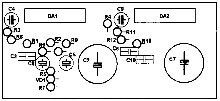
Rice. 3. Location of components for the bridge version of the inclusion of TDA7294 microcircuits.
To power such a power amplifier, you need a power source with a transformer with a power of at least 250-300 watts. In the rectifier circuit, it is advisable to install electrolytic capacitors of 10,000 μF or more on each arm.
Bridge circuit from the datasheet

Rice. 4. Bridge circuit for connecting two TDA7294 microcircuits (from the datasheet).
In bridge mode, the load resistance must be at least 8 ohms, otherwise the microcircuits will burn out from overcurrent!
Printed circuit board
Universal printed circuit board for two-channel and bridged power amplifier options.
The bridge circuit for switching on the UMZCH consists of two identical channels, in one of which the signal input is connected to ground, and the feedback input (leg 2) is connected through a 22K resistor to the output of the second channel.
Also, the 10th legs of the microcircuits (Mute) and the 9th legs (Stand-By) need to be connected to a mode control circuit assembled using resistors and capacitors (Figure 6).

Rice. 5. Printed circuit board for a power amplifier based on TDA7294 chips.
The boards have slight deviations (for the better) from the diagram from the datasheet:
- At the inputs of the microcircuits (pin 3), 4 µF capacitors are installed, not 0.56 µF;
- A 470 µF capacitor is connected between the 680 Ohm resistor (which goes to pin 2) and ground;
- The capacitors between legs 6 and 14 are 470 µF, not 22 µF;
- For power supply, instead of 0.22 µF capacitors, it is proposed to install 680 nF (0.68 µF);
In a bridge connection, pins 10 and 9 are connected together respectively and connected to the mode control circuit.

Rice. 6. Simple scheme control of Standby-Mute modes for TDA7294 chips.
To turn on the microcircuits (take them out of quiet and energy-saving modes), the “VM” and “VSTBY” contacts just need to be connected to the positive +Vs power supply pin.
This printed circuit board is universal; it can be used for both dual-channel and bridge modes of operation of the amplifier on TDA7294 chips. The ground wiring (GND) is very well done here, which will improve the reliability and noise immunity of the UMZCH.
Literature:
- Datasheet for the TDA7294 chip - Download (7-Zip archive, 1.2MB).
- FAQ for TDA7294 - cxem.net/sound/amps/amp129.php
Supplementing the TDA7294 microcircuit with powerful complementary transistors controlled from its output stage increases the rated output power of the UMZCH to 100 W with a 4 Ohm load. In addition to domestic transistors, more powerful imported ones can be recommended for this purpose. The author's use of a low-noise fan - a "cooler" from a computer processor - in the design made it possible to reduce the size of the heat sinks and amplifier.
The UMZCH based on the TDA7294 chip has gained well-deserved popularity among radio amateurs. At a minimum cost, you can assemble a high-quality UMZCH.
The amplifier version based on the TDA7294 chip turns out to be more reliable when operating with a real load, but its main specifications remain the same: the coefficient of nonlinear distortion, which is small for an output power of 5 W, increases to 0.5% at a power of more than 50 W. It is not possible to achieve an output power of more than 80 W with a 4 ohm load. The bridge circuit for connecting the microcircuit, recommended by the manufacturer, does not provide for the ability to work with a load with a resistance of 4 ohms.
The version of the amplifier shown here, its circuit shown in Fig. 1, solves the problem of increasing the output power and reducing the coefficient of nonlinear distortion with an output power of more than 50 W compared to a typical microcircuit circuit. To reduce the load on the output stage of the microcircuit, an additional push-pull repeater is built in at powerful bipolar transistors, which operate in mode B. There are no ladder-type distortions in the output stage because the output of the microcircuit is also connected to the load through a low-resistance resistor, and the OOS voltage is removed from the emitter circuit of additional transistors. Resistor R7 ensures rapid discharge of the capacitance of the emitter junctions of the output stage transistors.
Main technical characteristics:
Input impedance: 22 kOhm
Input voltage: 0.8V
Rated output power: 100W/4ohm
Reproducible frequency band: 20 – 20000 Hz
The disadvantage of the proposed UMZCH, in comparison with the version using a standard microcircuit connection circuit, is a steeper increase in nonlinear distortions at an output power close to the maximum. In a typical circuit, the output signal limitation has a “softer” character.
Simplified block diagram of TDA7294 shown in Fig. 1 allows us to make the following assumption. In the circuits of the output transistors of the microcircuit, resistive current sensors are included, therefore, when the output signal voltage is close to the supply voltage (when the current through powerful transistors microcircuit is maximum), the protection unit begins to smoothly limit the current in the load, field effect transistors output stage probably also contribute to softer clipping. The additional transistors of this UMZCH are not covered by such a tracking circuit, and a “hard” limitation of the output signal occurs, which is noticeable by ear.
A decrease in capacitance C6, C7 in comparison with that indicated in the circuit leads to unstable operation of the UMZCH at high power, but an increase in capacitance can lead to failure of transistors VT1, VT2, since when shorted in the load, the microcircuit protection unit does not always provide reliable protection for additional transistors until the fuses FU1, FU2 trip. The amplifier is powered by an unstabilized power supply from a 220 V network.
Not all parts purchased on radio markets are of high quality. There are microcircuits that are prone to self-excitation. In the described embodiment, self-excitation of some microcircuits must be eliminated by selecting capacitor C6.
In the UMZCH according to the scheme proposed here, even with slight self-excitation, “step” type distortions occur. If it is not possible to replace the “unsuccessful” microcircuit, the effect can be eliminated by soldering a capacitor with a capacity of 0.047-0.15 μF in parallel with resistor R7. Self-excitation is also eliminated by reducing the depth of feedback (increasing the resistance of resistor R3), while increasing the sensitivity of the amplifier.
Parts used in the amplifier:
- MLT resistors
- capacitors C1 - K73-17, KM-6; S2 – KT-1, KM-5; C8 – K73-17; SZ-S7 - K50-35 or imported.
- choke L1 - 25 turns of PEV-2 wire with a diameter of 1 mm - wound on a frame with a diameter of 5 mm in two layers.
Two amplifier channels are assembled on a printed circuit board made of one-sided foil fiberglass 2 mm thick; its drawing with the arrangement of elements is shown in Fig. 2 (the outline of the fans is conditionally transparent).

There is no space provided on the printed circuit board for blocking capacitors C9, C10. The use of transistors that differ significantly in the base current transfer coefficient has practically no effect on reliability and sound quality.
The absence of quiescent current allows you to use a fan (“cooler”) from a Pentium processor to cool the heat sinks of both channels of the amplifier. The board and fans must be installed so that the flow of warm air does not heat other parts of the amplifier.
Powerful transistors are mounted parallel to the plane of the printed circuit board with a metal surface of the heat sink to the cooler. On the flat side of the cooler, it is necessary to drill through holes with a diameter of 2.5 mm, coinciding with the holes in the printed circuit board, then cut the MZ thread. Through the holes in the board, the fan is pressed against the transistors with screws. Thin mica spacers must be placed on them and lubricated with heat-conducting paste.
Under the heads of the screws on the side of the tracks, you need to place washers with a diameter of 10-12 mm or a small metal plate in order to firmly press the transistors to the surface of the heat sink. Between printed circuit board and transistors, place thin cardboard 0.5-0.8 mm thick, it will ensure uniform pressing of the transistors to the plane of the fan, since their thickness is not always the same, even for those manufactured in the same production batch.
The DA1 chip is located on an additional heat sink with an effective surface area of at least 50 cm 2 .


It is advisable to “strengthen” the tracks on the printed circuit board through which the supply voltage is supplied to the output transistors by soldering tinned copper wire with a diameter of about 1 mm along them.
An amplifier assembled from serviceable parts does not require adjustment and can be repeated even by novice radio amateurs. Operation for two years showed its high reliability.
With new wiring, as well as with mounting the microcircuit and transistors on one radiator.
The article is dedicated to lovers of loud and high-quality music. TDA7294 (TDA7293) is a low-frequency amplifier microcircuit manufactured by the French company THOMSON. The circuit contains field-effect transistors, which provides high quality sound and soft sound. A simple circuit with few additional elements makes the circuit accessible to any radio amateur. A correctly assembled amplifier from serviceable parts begins to work immediately and does not require adjustment.

The audio power amplifier on the TDA 7294 chip differs from other amplifiers of this class:
- high output power,
- wide supply voltage range,
- low percentage of harmonic distortion,
- "soft sound,
- few “attached” parts,
- low cost.
Can be used in amateur radio audio devices, when modifying amplifiers, speaker systems, audio equipment, etc.
The picture below shows typical circuit diagram power amplifier for one channel.


The TDA7294 microcircuit is a powerful operational amplifier, the gain of which is set by a negative feedback circuit connected between its output (pin 14 of the microcircuit) and the inversion input (pin 2 of the microcircuit). The direct signal is supplied to the input (pin 3 of the microcircuit). The circuit consists of resistors R1 and capacitor C1. By changing the values of resistance R1, you can adjust the sensitivity of the amplifier to the parameters of the pre-amplifier.
Block diagram of the amplifier on TDA 7294

Technical characteristics of the TDA7294 chip
Technical characteristics of the TDA7293 chip
Schematic diagram of the amplifier on TDA7294

To assemble this amplifier you will need the following parts:
1. Chip TDA7294 (or TDA7293)
2. Resistors with a power of 0.25 watt
R1 – 680 Ohm
R2, R3, R4 – 22 kOm
R5 – 10 kOhm
R6 – 47 kOhm
R7 – 15 kOhm
3. Film capacitor, polypropylene:
C1 – 0.74 mkF
4. Electrolytic capacitors:
C2, C3, C4 – 22 mkF 50 volt
C5 – 47 mkF 50 volt
5. Double variable resistor - 50 kOm
A mono amplifier can be assembled on one chip. To assemble a stereo amplifier, you need to make two boards. To do this, we multiply all the necessary parts by two, except for the dual variable resistor and power supply. But more on that later.
Amplifier circuit board based on TDA 7294 chip
The circuit elements are mounted on a printed circuit board made of single-sided foil fiberglass.

A similar circuit, but with a few more elements, mainly capacitors. The switch-on delay circuit at the “mute” pin 10 input is enabled. This is done for a soft, pop-free turn on of the amplifier.


A microcircuit is installed on the board, from which unused pins have been removed: 5, 11 and 12. Install using a wire with a cross-section of at least 0.74 mm2. The chip itself must be installed on a radiator with an area of at least 600 cm2. The radiator should not touch the amplifier body in such a way as there will be a negative supply voltage on it. The housing itself must be connected to a common wire.
If you use a smaller radiator area, you need to make forced airflow by placing a fan in the amplifier case. The fan is suitable from a computer with a voltage of 12 volts. The microcircuit itself should be attached to the radiator using heat-conducting paste. Do not connect the radiator to live parts, except for the negative power bus. As mentioned above, the metal plate at the back of the microcircuit is connected to the negative power circuit.
Chips for both channels can be installed on one common radiator.
Power supply for amplifier.
The power supply is a step-down transformer with two windings with a voltage of 25 volts and a current of at least 5 amperes. The voltage on the windings should be the same and so should the filter capacitors. Voltage imbalance should not be allowed. When supplying bipolar power to the amplifier, it must be supplied simultaneously!

It is better to install ultra-fast diodes in the rectifier, but in principle, ordinary ones like D242-246 with a current of at least 10A are also suitable. It is advisable to solder a capacitor with a capacity of 0.01 μF in parallel to each diode. You can also use ready-made diode bridges with the same current parameters.
Filter capacitors C1 and C3 have a capacity of 22,000 microfarads at a voltage of 50 volts, capacitors C2 and C4 have a capacity of 0.1 microfarads.
The supply voltage of 35 volts should only be with a load of 8 ohms; if you have a load of 4 ohms, then the supply voltage must be reduced to 27 volts. In this case, the voltage on the secondary windings of the transformer should be 20 volts.
You can use two identical transformers with a power of 240 watts each. One of them serves to obtain positive voltage, the second - negative. The power of the two transformers is 480 watts, which is quite suitable for an amplifier with an output power of 2 x 100 watts.
Transformers TBS 024 220-24 can be replaced with any others with a power of at least 200 watts each. As written above, the nutrition should be the same - transformers must be the same!!! The voltage on the secondary winding of each transformer is from 24 to 29 volts.
Amplifier circuit increased power on two TDA7294 chips in a bridge circuit.

According to this scheme, for the stereo version you will need four microcircuits.
Amplifier specifications:
- Maximum output power at 8 Ohm load (supply +/- 25V) - 150 W;
- Maximum output power at a load of 16 Ohms (supply +/- 35V) - 170 W;
- Load resistance: 8 - 16 Ohms;
- Coef. harmonic distortion, at max. power 150 watts, e.g. 25V, heating 8 Ohm, frequency 1 kHz - 10%;
- Coef. harmonic distortion, at a power of 10-100 watts, for example. 25V, heating 8 Ohm, frequency 1 kHz - 0.01%;
- Coef. harmonic distortion, at a power of 10-120 watts, for example. 35V, heating 16 Ohm, frequency 1 kHz - 0.006%;
- Frequency range (with a non-frequency response of 1 db) - 50Hz ... 100kHz.
View of the finished amplifier in a wooden case with a transparent plexiglass top cover.

For the amplifier to operate at full power, you need to apply the required signal level to the input of the microcircuit, and this is at least 750 mV. If the signal is not enough, then you need to assemble a pre-amplifier for boosting.
Pre-amplifier circuit on TDA1524A

Setting up the amplifier
A properly assembled amplifier does not need adjustment, but no one guarantees that all parts are absolutely in good working order; you need to be careful when turning it on for the first time.
The first switch-on is carried out without load and with the input signal source turned off (it is better to short-circuit the input with a jumper). It would be nice to include fuses of about 1A in the power circuit (both in the plus and minus between the power source and the amplifier itself). Briefly (~0.5 sec.) Apply the supply voltage and make sure that the current consumed from the source is small - the fuses do not burn out. It is convenient if the source has LED indicators - when disconnected from the network, the LEDs continue to light for at least 20 seconds: the filter capacitors are discharged for a long time by the small quiescent current of the microcircuit.
If the current consumed by the microcircuit is large (more than 300 mA), then there can be many reasons: short circuit in installation; poor contact in the “ground” wire from the source; “plus” and “minus” are confused; the pins of the microcircuit touch the jumper; microcircuit is faulty; capacitors C11, C13 are soldered incorrectly; capacitors C10-C13 are faulty.
Having made sure that everything is normal with the quiescent current, we safely turn on the power and measure the constant voltage at the output. Its value should not exceed +-0.05 V. High voltage indicates problems with C3 (less often with C4), or with the microcircuit. There have been cases when the “ground-to-ground” resistor was either poorly soldered or had a resistance of 3 kOhms instead of 3 ohms. At the same time, the output was constant 10...20 volts. Connecting a voltmeter to the output alternating current, make sure that the alternating voltage at the output is zero (this is best done with the input closed, or simply with the input cable not connected, otherwise there will be noise at the output). The presence of alternating voltage at the output indicates problems with the microcircuit, or circuits C7R9, C3R3R4, R10. Unfortunately, conventional testers often cannot measure the high-frequency voltage that appears during self-excitation (up to 100 kHz), so it is best to use an oscilloscope here.
All! You can enjoy your favorite music!
