Color music on LEDs with your own hands. Homemade color music from LEDs. Assembling color music for a car
Almost all color music devices of sufficient power are designed for the use of conventional incandescent lamps. There are also CMU circuits on LEDs on the Internet, but they are usually for low-power LEDs. How to connect 50-100 watt LEDs to such a device? You can take as a basis one very good color music scheme (also with sound control via a microphone) and slightly modify the output part - get the desired result.
CMU circuit for high-power LEDs
 Schematic diagram of the CMU for 220V
  Schematic diagram of the CMU for 12V


The electrical power supply for the input part of the frequency processing is made on a piece of a universal board. The transformer was taken from some kind of radio. It is ideal because it is symmetrical and has 10V windings. BT151/600 thyristors were used as powerful switches, with a margin so that they would not burn out from high currents.


The circuit can be made completely isolated from the network if the executive part is used using triacs and optocouplers.


When testing, temporarily install resistors of rated resistance and power from 10 W instead of LEDs.
CMU with 12 V LED strips
If you want to use 12 V LED strips in the CMU direct current, then you can power the entire circuit with the same 12 volts from the pulse network driver, and assemble the output part using powerful field-effect transistors.

A version of the diagram is shown above. Here resistor R2 sets the current limiting of the LED strip (or a powerful single LED).
By the way, when installing individual high-power LEDs, for example 100 watts (32 V at 3 A), supply the supply voltage from the driver through the LED to the drain field effect transistor(after making sure from the datasheet that it can withstand such U/I parameters), and use the resistor indicated above to set the desired current level.


The body is made of wood (easier to find the material and easier to process). The holes for the lamps are drilled with large cutters. Naturally, on the front there are all the necessary knobs for adjusting signal levels and HF-MF-LF channels and a power button.
Today we were in the Auchan store and bought MCM color music for home disco. It was simply impossible to resist: at the usual price of 1,500 rubles, the device was sold for 399! Of course, this shrill Chinese contraption can't even remotely compare to this a color and music installation that operates according to very specific laws. The purchased product is rather a simple “flashing light”. However, if you just need to organize a small party at home without going into details of the operating principle, then it will be quite suitable for organizing lighting effects. By at least my 4 year old son was absolutely delighted with it. In this article I would like to leave review about MCM color music and meditate a little on the topic of color music installations as such.
Previously, color music was made by hand
During the Soviet era, there was a lot of tension with good audio equipment. Of course, there were first-class stereo recorders, for example, Rostov-105. Their sound quality was excellent, especially if you record music from a good source onto German Agfa magnetic tape at a speed of 19 (centimeters per second).

Reel-to-reel stereo tape recorder Rostov 105. Photo from the Internet
Alas, all this was very expensive and practically inaccessible to ordinary Soviet workers and employees. Well, judge for yourself, with a salary of 150 rubles a month, buying a stereo recorder for 400 rubles was an unaffordable luxury. They could have easily “taken it apart” at the trade union committee and, at best, made it look like it. At worst - a Komsomol or party card "on the table." But we also had to buy speakers, which were also not cheap.
Approximately the same situation was with color and music installations. Homemade household devices There was almost no factory production, and large professional ones were again simply unaffordable in price.
At that time, the vast majority of "color music" were assembled at home by hand using radio parts purchased in the store " Young technician" according to schemes published in the magazine "Technology for Youth" or "Model Designer".
It would never occur to modern youth to make color music with their own hands. After all, you can go to the store and buy ready-made ones. Or even download a program from the Internet and turn your computer monitor into an excellent color and music screen, which will also have a bunch of different settings.
Almost no one today “etches” printed circuit boards in a special solution, exchanges or otherwise obtains scarce radio components, solders circuits, or racks their brains over the design of the light part of the device.
But at one time it was especially chic to make your own color music, which not only would not explode the first time you turned it on, but would work, and in strict accordance with all the rules. By the way, about the rules.
How real color music works
Now many people don’t even know this. And before, real radio amateurs and specialists in such devices had a great idea of what was what. The fact is that multi-colored light bulbs in color music should not blink chaotically, not when they want, but in exact accordance with frequency response sounding music.
Let's look at this with an example, if you're at all interested.
Let's take some song and try to sort it into frequencies.
What "booms" is low sound frequencies. Their sources can be a drummer, a bass guitar, and modern synthetic sounds that make the dishes rattle in the sideboard. IN speaker systems The largest speakers are responsible for high-quality reproduction of low frequencies. So, when low sound frequencies appear in the general spectrum, red lamps should light up in the color music installation. Why? Simply because red is also the lowest frequency color in the visible light range. When creating the concept of a color music installation, the inventors decided to make sure that low-frequency sound was accompanied by low-frequency light.
Thus, if you imagine an ordinary classic rock or pop composition, then flashes of red color indicated the rhythm of the drummer and the bass intro.
At the other pole is the high-frequency component of music. These are all whistling sounds, like hitting cymbals in a drum kit. When a high-frequency component appears in the general musical background, the blue lamps should flash. Again "why"? Because blue is one of the highest frequencies in the visible range. Violet would have been even more suitable from the point of view of frequency response, but for some reason the inventors settled on blue. That's how it happened.
Anything within the mid range should be accompanied by green flashes.
Thus, in real color music, the sound is, as it were, colored and visualized in full accordance with the frequency characteristics.
From this point of view, modern color music installations often look like simple flashing lights, which either implement the so-called “running light” or simply randomly turn on lamps of one color or another. Although there are pleasant exceptions today.
How real color music works
I dare to show you an electrical circuit diagram. Alas, only specialists can understand it at first glance, so we will have to explain something:

images from the Internet
So on the right are the lamps. You recognized them. These are ordinary light bulbs that are screwed into chandeliers. Moreover, previously it was impossible to simply go to the store and buy red, green and blue lamps. Therefore, at that time, ordinary or, even better, matte lamps of the required power were purchased. Then their flasks had to be painted.
The most accessible paint was ordinary ink from ballpoint pens. We took the rod and carefully removed the metal tip with the ball. Then they blew ink onto the paper. And then they started painting the light bulbs. And not with brushes or sponges - after all, the ink was quite thick - you had to paint with your finger. Yes Yes! They dipped their index finger into a squeezed-out ink blot on paper and began to spread the ink across the surface of the light bulb. When someone came to school the next morning with multi-colored fingers, we immediately understood the reason and asked: “Well, did it work?”
Now you can go to an electrical goods store and buy everything you need. And then there were different times. We had to use what was at hand. Now it already looks funny and ridiculous. But before it was almost the only way receive COLOR LAMPS.
To the left of the light bulbs in the diagram are thyristors - the most scarce and expensive parts of color music. They made it possible to transfer electricity from the socket to the light bulbs. They were like shutters, which "opened" on command from the rest electrical diagram and applied voltage from the socket to the corresponding lamp. The lamp lit up while the thyristor was “open”. The thyristors became very hot during operation, so they had to be installed on radiators for additional cooling.
The rest of the circuit, consisting of resistors (red) and capacitors (silver), was responsible for decomposing the input signal from the tape recorder into frequency components and opening the thyristor gates (lighting the light bulbs) when a signal of a certain frequency range appeared at the input.
If interested, look at the colored wires. It will become clear which part of the circuit is responsible for the low frequency (red), mid frequency (green) and high frequency (blue) signal.
A separate variable resistor (at the top of the circuit) made it possible to adjust the sensitivity of the circuit. The fact is that different tape recorders and players had different signal power at the linear output. Therefore, it was impossible to do without this possibility of smooth adjustment. Otherwise, it could happen that all the lamps would be on all the time without any blinking if the signal was strong, or, on the contrary, would not turn on at all if the input signal was weak.
Now I would like to apologize to real professionals in radio engineering for such a free explanation of the principle of operation of color music. Do not worry. Most readers won't pay any attention to it anyway. I was just trying to explain it in a way that everyone could understand.
Thus, real color music consisted of two parts:
- control unit - the electrical circuit itself
- light block - lamps
When relatively inexpensive household installations went on sale, they looked, for example, like this:

images from the Internet
Color music on starters
You will laugh, but in those distant Soviet times, not everyone was able to get thyristors. That was the shortage.
But I still wanted to have color music!
And then another solution came to the aid of those suffering: a color and music installation with electric starters.
In fact, this was originally a flashing light circuit for a garland. Now they are sold with built-in flashers, which, moreover, contain several different programs. And then the Christmas tree garland was simply plugged into an outlet and burned constantly (like a stupid thing).
All self-respecting radio amateurs at that time knew how to make a very simple flasher. Here is her diagram:

images from the Internet
And this is what the device looked like in real life:

images from the Internet
It's simple. No scarce parts. There are only two elements - a starter (they are used in luminaires with lamps daylight) and a capacitor. The garland was plugged into a socket on the device, and the device itself was plugged into the network. The Christmas tree garland began to blink. Moreover, the blinking was chaotic both in duration and frequency.
Thus, without much hassle and expense, a device was obtained that could be used to organize home (and not only home) parties. The lamps turned on chaotically and completely independently of each other. There were moments when they burned all together, sometimes in pairs, sometimes just one. Sometimes they all turned off at the same time and the room was completely dark for a moment.
Alas, there was no connection whatsoever with the frequency characteristics of the music. Even during a pause between songs, the device continued to flash regularly. But... you know, it was very funny to follow the random blinking and compare it with the music playing. At some moments there were random coincidences with the rhythm or with the same frequency characteristic. But, of course, this was the exception rather than the rule.
Of course, this was not real color music, but in the absence of fish, as they say, even a crab is a fish.
30 years have passed since those ancient times. Now anyone can simply go to a store (an ordinary supermarket) and buy a color and music installation for a certain amount. Of course, this is very cool. It’s just a little pity that modern boys can no longer feel that indescribable happiness when the color music made by your hands suddenly “came to life” and began to work, and exactly the way it SHOULD!
Color music MCM with microphone
Let's go back to today. As I already said, the reason for this article was the purchase color and music installation MCM.
I can't speak for everyone, but if something like this fell into my hands at the age of 16, I would be one of the happiest people. Then there were slightly different values: imported factory-made color music with real color lamps and a microphone for analyzing the sound of music would have created a real sensation among fellow boys! Judge for yourself:


In fact, there is everything you need here: three lamps, and not painted with fingers dipped in ink from a ballpoint pen, but real ones, made of colored glass.
There is a control unit with a tempo and sensitivity regulator.
There is a microphone that picks up the music and transmits it to electronic circuit, which, in fact, should operate in the same way as the above thyristor circuit.
In addition, the design of MSM color music was very different from the homemade boxes in which radio amateurs in the old days packaged their products.

As you can see, the color music body can be disassembled into individual components. True, placing them in different corners of the room simply won’t work - the wires are short. But the collapsible body already gives some room for maneuver, and the wires, if necessary, can be extended.
I wonder what it says on the box LED color and music installation. An obvious lie. The design uses conventional 60-watt incandescent lamps. Therefore, during operation, the device begins to pose some danger to others. I can imagine what will happen if some tipsy guest “loses control” and comes into contact with the fiery lamp of the color music :).
How does MSM color music work?
Rather than describe for a long time, it is better to show. In this video, color music first works in the “running fire” mode, and then I turn on the microphone and a certain “reaction” to the sounding music appears. How much it can satisfy you - decide for yourself.
Conclusion
For real radio engineering enthusiasts, not to mention professionals, MCM color music is a real mockery of the best engineering feelings. With its free interpretation of the frequency range and clumsy response to playing music, the device can drive experienced users into a frenzy.
Therefore, if you want to enjoy the exact match of sound and color images, then I do not recommend buying this product. The best decision for you - to assemble the device yourself. You will get real pleasure from both the assembly process and the work of your color music.
If you just need to highlight a children’s party or a completely adult corporate event, then a couple of these devices will cope with the task. Everyone will have a lot of fun... there is only one BUT.
If a real engineer turns out to be at the holiday, I don’t mean by his diploma, but by his essence, he will leave the holiday upset and then, perhaps, even get sick. Because in his view, MCM color music will be a real outrage against the very concept of color music devices. There is certainly some humor in this phrase. However, I remember an incident when I myself left a concert only because two guitars were “not in tune” - that is, one string of one of the guitars was tuned incorrectly. No fun! One frustration!
So, I told you everything, showed you, and you decide whether to buy such color music.
It's hard to find a person who doesn't like listening to music. To satisfy this desire, high-quality music centers, speakers and other devices are purchased. To get even more pleasure, many people think about creating special color effects that can decorate any sound and create a romantic atmosphere on a date or a fun mood when organizing a holiday party. Color music, like music centers, can be purchased, or you can make it yourself. The best option— make color music using LEDs with your own hands according to one of the proposed schemes.
Advantages of LED products
The modern electronics market presents a wide variety of LED strips that have a wide variety of color effects. With their help, you can create high-quality spot lighting; it is possible to create light music with flashing or blurry effects.
Unlike conventional light bulbs, LEDs are characterized by big amount positive characteristics. Among the main advantages of LED strips are:
- wide and varied range of colors;
- rendering rich colors;
- different design options - rulers, modules, discrete elements, RGB strips;
- high response speed;
- minimum amount of energy consumed.
The ribbons can be used at home, in clubs and cafes, and can be used to effectively illuminate shop windows. This article will describe the option in more detail. LED color music for normal home use.
Simple circuit with one lamp
To begin with, it is worth studying simple diagram color music. This is a device that consists of one LED, transistor and resistor. Power for such color music can be supplied from a constant current source with a voltage of 6-12 volts. The device operates on the principle of an amplification stage with a common emitter. The impact in the form of a signal varying in frequency and amplitude arrives at the main base. As soon as the oscillation frequency exceeds a certain threshold value, the transistor opens and the LED immediately flashes.

This scheme of simple color music on LEDs has one drawback - the rate of blinking of the LED depends entirely on the level of production sound signal. In other words, the light effect will only be activated at a certain level of output music center volume. When the sound intensity decreases, the glow will be constant with occasional winks.
Scheme with one-color ribbon
This color music on a transistor is assembled using an LED strip in the load. To organize such color music, you will need to increase the power supply to 12 V, find and install a transistor with a maximum collector current that exceeds the load current, and you will also need to recalculate the total value of the resistor. This color music is quite simple, made on one single-color LED strip and is ideal for beginner radio amateurs. You can assemble it without any problems at home.
Simple three-channel circuit
To get color music that is free of all the disadvantages listed above, you should use a special three-channel sound converter. This circuit is powered by LED strip constant voltage 9 V and is able to effectively illuminate one or two LEDs in each channel. Among the main structural elements that characterize such a color-musical scheme are:
- three independent amplifier stages, which are assembled using transistors of the KT315 (KT3102) category;
- LEDs of different colors are included in the transistor load;
- For the pre-amplification element, a network small step-down transformer can be used.

The incoming signal is fed to the secondary winding of the transformer, which in turn performs two main functions - it decouples two devices at the galvanic level, and also amplifies the sound from the main linear output. After this, the signal is fed to three parallel and connected filters assembled on the basis of RC circuits. They operate on an individual frequency band, which directly depends on the value of the capacitor and resistor.
Color music with RGB tape
This attachment circuit operates on 12 volts and is ideal for installation on a car. This color music optimally combines the main functions of the previously discussed schemes and is able to work both in the lamp mode and in the color music mode. The second mode is achieved through special contactless control of the RGB strip via a microphone. As for the lamp mode, it is based on the simultaneous launch of the green, red and blue LED at full power. The mode can be selected using a special switch located on a special board.
To understand how this attachment works, it is worth studying its sequence of actions. The main source of the signal here is a microphone, which converts sound vibrations emanating from the phonogram. The received signal is insignificant and therefore requires amplification. This can be achieved by using a transistor or a special operational amplifier. After this, the automatic AGC level controller starts. It effectively keeps sound fluctuations within reasonable limits and prepares it for subsequent processing. Built-in filters divide the signal into three parts, each of which operates in one specific frequency range. Finally, you just need to amplify the previously prepared current signal. For this purpose, special transistors are used that operate in key mode.

Purchase of a ready-made CMU
If you don’t want to make a color music system for use at home, you can purchase a CMU, that is, a color music installation. This is a ready-made functional solution that includes a controller. It will process the sound, converting it into a light and music visual representation. In the process of reproducing the light, its intensity and color scheme will change, thereby creating the effect of a real disco. The CMU device also includes a panel with built-in diodes.
These devices may be based on a spectral decomposition into frequencies, where each of them will have a specific color scheme or preset adjustments with a variety of effects and their alternation. They can be configured using the included remote control.
Important! Modern CMUs are very simple to install and configure. This perfect solution for organizing a home party or disco.
Conclusion
There are quite a lot of schemes for independently performing color music settings. You can choose a fairly simple option, where the color of the RGB tape will simply change, to quite complex ones, which in the process of work will create a large number of different effects, overflows and attenuations. Depending on your skills, you can choose and execute the appropriate option. It is enough to work a little and create something truly unique; it will be lighting equipment that delights with the shimmer of a wide variety of color shades. Also, do not forget that there is always the opportunity to buy a ready-made color music solution and fill your home with color shades and joy.
This LED color music is suitable for those who listen to music on the computer. It can be placed inside the case and it will be illuminated to the beat of the music.
The color music scheme is very simple and does not present any difficulties.
 Required components:
1. 4 LEDs (any color) 3mm
2. P2 plug
3. 2 position switch
4. Bipolar transistor TIP31
5. The box (if needed) can also be placed directly in the computer case
6. Soldering iron
7. Cable
 We connect 4 LEDs to +12 V of the computer, connect the anode to a 2-position switch, which in turn connects to bipolar transistor TIP31. We connect the two unused ends of the transistor directly to the terminals of the plug for headphones or speakers P2.
We install all the assembled components in a box (box), or directly into the computer case - it’s up to everyone at their own discretion. We made holes for the LEDs, switch and plug.

Installation of LED color music in a box
Let's connect the LEDs, transistor and switch
1 of 2

Connecting LEDs

General assembled view with transistors
Next comes the most interesting part. It is necessary to solder the LEDs together, the transistor and the switch. From the photographs it is clear without words. The only thing is that we had to select the length of the conductors so that they would fit in the box.
We connect the common negative from the LEDs to the middle contact of the switch. From the switch, one of the positions is connected to the middle pin of the transistor, connect the second position according to the color music diagram that we presented above.
Installation of wires to plug P2
Final stage
1 of 2

Installation of diode color music circuit

Soldered plug
If we disassemble the headphone plug, we can see three connectors inside - left and right channels, ground. We connect one of the channels to the left pin of the Tip31 transistor. If P2 is connected through the left channel and it does not “beat” with the computer output, then our circuit will not work. Therefore, immediately decide correctly or experiment. Ground (usually a long connector) should be connected to the right pin of the transistor.
One of the switch pins should be connected to ground from the transistor. With this connection, the LEDs will start blinking if there is any signal at the output. If there is no signal coming from connector P2, if there is a signal on the other side, they will light up constantly.
We mount everything in the box, connect it and check its functionality.
Almost every novice radio amateur, and not only others, had a desire assemble a color music console or running fire to add variety to your music listening experience in the evening or on holidays. In this article we will talk about a simple color music console assembled on LEDs, which even a novice radio amateur can assemble.
1. The operating principle of color music consoles.
Operation of color music consoles ( CMP, CMU or SDU) is based on frequency division of the spectrum of an audio signal with its subsequent transmission through separate channels low, average And high frequencies, where each channel controls its own light source, the brightness of which is determined by the vibrations of the sound signal. The end result of the console's operation is to obtain a color scheme that matches the piece of music being played.
To obtain a full gamut of colors and the maximum number of color shades, color music consoles use at least three colors:

The frequency spectrum of the audio signal is divided using LC- And RC filters, where each filter is tuned to its own relatively narrow frequency band and passes through only vibrations of this part of the audio range:
1
. Low pass filter(low-pass filter) transmits vibrations with a frequency of up to 300 Hz and the color of its light source is chosen red;
2
. Mid Pass Filter(PSC) transmits 250 – 2500 Hz and the color of its light source is chosen green or yellow;
3
. High pass filter(HPF) transmits from 2500 Hz and above, and the color of its light source is chosen blue.

There are no fundamental rules for choosing the bandwidth or color of the lamps, so each radio amateur can use colors based on the characteristics of his perception of color, and also change the number of channels and frequency bandwidth at his own discretion.
2. Schematic diagram of a color music console.
The figure below shows a diagram of a simple four-channel color and music set-top box assembled using LEDs. The set-top box consists of an input signal amplifier, four channels and a power supply that supplies the set-top box with AC power.

Signal audio frequency supplied to contacts PC, OK And General connector X1, and through resistors R1 And R2 goes to the variable resistor R3, which is a regulator of the input signal level. From the middle terminal of the variable resistor R3 sound signal through a capacitor C1 and resistor R4 enters the input preamp, assembled on transistors VT1 And VT2. The use of an amplifier made it possible to use the set-top box with almost any audio source.
From the output of the amplifier, the audio signal is supplied to the upper terminals of trimming resistors R7,R10, R14, R18, which are the load of the amplifier and perform the function of adjusting (tuning) the input signal separately for each channel, and also set the desired brightness of the channel LEDs. From the middle terminals of the trimming resistors, the audio signal is supplied to the inputs of four channels, each of which operates in its own audio range. Schematically, all channels are designed identically and differ only in RC filters.
Per channel higher R7.
The channel bandpass filter is formed by a capacitor C2 and passes only the high-frequency spectrum of the audio signal. Low and medium frequencies do not pass through the filter, since the capacitor resistance for these frequencies is high.

Passing the capacitor, the high-frequency signal is detected by a diode VD1 and is fed to the base of the transistor VT3. The negative voltage appearing at the base of the transistor opens it, and a group of blue LEDs HL1 — HL6 included in its collector circuit are ignited. And the greater the amplitude of the input signal, the stronger the transistor opens, the brighter the LEDs burn. To limit the maximum current through the LEDs, resistors are connected in series with them R8 And R9. If these resistors are missing, the LEDs may fail.
Per channel average frequency signal is supplied from the middle terminal of the resistor R10.
The channel bandpass filter is formed by a circuit С3R11С4, which for low and higher frequencies has significant resistance, therefore, to the base of the transistor VT4 Only mid-frequency oscillations are received. LEDs are included in the collector circuit of the transistor HL7 – HL12 Green colour.
Per channel low frequency signal is supplied from the middle terminal of the resistor R18.
The channel filter is formed by a circuit С6R19С7, which attenuates signals of medium and high frequencies and therefore to the base of the transistor VT6 Only low frequency vibrations are received. The channel load is LEDs HL19 – HL24 Red.
For a variety of colors, a channel has been added to the color music console yellow colors. The channel filter is formed by a circuit R15C5 and operates in the frequency range closer to low frequencies. The input signal to the filter comes from a resistor R14.
Feeds color music console constant voltage 9V. The power supply unit of the set-top box consists of a transformer T1, diode bridge made on diodes VD5 – VD8, microcircuit voltage stabilizer DA1 type KREN5, resistor R22 and two oxide capacitors C8 And C9.
The alternating voltage rectified by the diode bridge is smoothed by an oxide capacitor C8 and goes to the voltage stabilizer KREN5. From the output 3 microcircuit, a stabilized voltage of 9V is supplied to the set-top box circuit.
To obtain an output voltage of 9V between the negative bus of the power supply and the output 2 chip included resistor R22. By changing the resistance value of this resistor, the desired output voltage is achieved at the pin 3 microcircuits.
3. Details.
The console can use any fixed resistors power 0.25 - 0.125 W. The figure below shows resistor values that use colored stripes to indicate the resistance value:

Variable resistor R3 and tuning resistors R7, R10, R14, R18 of any type, as long as they fit the size of the printed circuit board. In the author's version of the design, a domestic variable resistor of the SP3-4VM type and imported trimming resistors were used.

Permanent capacitors can be of any type, and are designed for an operating voltage of at least 16 V. If difficulties arise in purchasing a C7 capacitor with a capacity of 0.3 μF, it can be composed of two connected in parallel with a capacity of 0.22 μF and 0.1 μF.
Oxide capacitors C1 and C6 must have an operating voltage of at least 10 V, capacitor C9 not below 16 V, and capacitor C8 not below 25 V.

Oxide capacitors C1, C6, C8 and C9 have polarity, therefore, when mounting on a breadboard or printed circuit board this must be taken into account: for Soviet-made capacitors, the positive terminal is indicated on the case; for modern domestic and imported capacitors, the negative terminal is indicated.

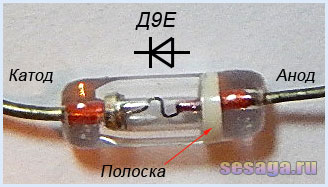
Diodes VD1 – VD4 any from the D9 series. A colored stripe is applied to the diode body on the anode side, identifying the letter of the diode.
As a rectifier assembled on diodes VD5 - VD8, a ready-made miniature diode bridge is used, designed for a voltage of 50V and a current of at least 200 mA.

If you use rectifier diodes instead of a ready-made bridge, you will have to slightly adjust the printed circuit board, or even move the diode bridge outside the main board of the set-top box and assemble it on a separate small board.
For self-assembly of the bridge, the diodes are taken with the same parameters as the factory bridge. Any rectifier diodes from the KD105, KD106, KD208, KD209, KD221, D229, KD204, KD205, 1N4001 - 1N4007 series are also suitable. If you use diodes from the KD209 or 1N4001 - 1N4007 series, then the bridge can be assembled directly from the printed circuit board directly on the contact pads of the board.
LEDs are standard with yellow, red, blue and green colors. Each channel uses 6 pieces:

Transistors VT1 and VT2 from the KT361 series with any letter index.

Transistors VT3, VT4, VT5, VT6 from the KT502 series with any letter index.

Voltage stabilizer type KREN5A with any letter index ( imported analogue 7805). If you use nine-volt KREN8A or KREN8G (imported analogue 7809), then resistor R22 is not installed. Instead of a resistor, a jumper is installed on the board, which will connect the middle pin of the microcircuit to the negative bus, or this resistor is not provided at all during the manufacture of the board.

To connect the set-top box to the sound source, a three-pin jack connector is used. The cable is taken from a computer mouse.

Power transformer - ready-made or home-made with a power of at least 5 W with a voltage on the secondary winding of 12 - 15 V at a load current of 200 mA.
In addition to the article, watch the first part of the video, which shows the initial stage of assembling a color music console
This ends the first part.
If you are tempted make color music using LEDs, then select the parts and be sure to check the serviceability of diodes and transistors, for example. And we will carry out the final assembly and configuration of the color and music console.
Good luck!
Literature:
1. I. Andrianov “Attacks for radio receivers.”
2. Radio 1990 No. 8, B. Sergeev “Simple color and music consoles.”
3. Operating manual for the “Start” radio designer.
