How many terminals does the diode have? What is a diode, zener diode, varicap, thyristor, LED - their types and applications. Materials for making diodes
A diode is one of the types of devices designed on a semiconductor basis. It has one p-n junction, as well as anode and cathode terminals. In most cases, it is designed for modulation, rectification, conversion and other actions with incoming electrical signals.
Principle of operation:
- Electricity acts on the cathode, the heater begins to glow, and the electrode begins to emit electrons.
- Between two electrodes an electric field is generated.
- If the anode has a positive potential, then it begins to attract electrons to itself, and the resulting field is a catalyst for this process. In this case, an emission current is generated.
- Between electrodes a negative spatial charge is formed that can interfere with the movement of electrons. This happens if the anode potential is too weak. In this case, some of the electrons are unable to overcome the influence of the negative charge, and they begin to move in the opposite direction, returning to the cathode again.
- All electrons, which reached the anode and did not return to the cathode, determine the parameters of the cathode current. Therefore, this indicator directly depends on the positive anode potential.
- Flow of all electrons, which were able to get to the anode, is called the anode current, the indicators of which in the diode always correspond to the parameters of the cathode current. Sometimes both indicators can be zero; this happens in situations where the anode has a negative charge. In this case, the field that arises between the electrodes does not accelerate the particles, but, on the contrary, slows them down and returns them to the cathode. The diode in this case remains in a locked state, which leads to an open circuit.

Device

Below is detailed description diode devices, studying this information is necessary for further understanding of the principles of operation of these elements:
- Frame is a vacuum cylinder that can be made of glass, metal or durable ceramic varieties of material.
- Inside the cylinder there are 2 electrodes. The first is a heated cathode, which is designed to ensure the process of electron emission. The simplest cathode in design is a filament with a small diameter, which heats up during operation, but today indirectly heated electrodes are more common. They are cylinders made of metal and have a special active layer capable of emitting electrons.
- Inside the cathode indirect heat there is a specific element - a wire that glows under the influence electric current, it's called a heater.
- Second electrode is the anode, it is necessary to accept the electrons that were released by the cathode. To do this, it must have a potential that is positive relative to the second electrode. In most cases, the anode is also cylindrical.
- Both electrodes vacuum devices are completely identical to the emitter and base of the semiconductor variety of elements.
- For making a diode crystal Silicon or germanium is most often used. One of its parts is p-type electrically conductive and has a deficiency of electrons, which is formed by an artificial method. The opposite side of the crystal also has conductivity, but it is n-type and has an excess of electrons. There is a boundary between the two regions, which is called a p-n junction.
Such features of the internal structure give diodes their main property - the ability to conduct electric current in only one direction.
Purpose
 Below are the main areas of application of diodes, from which their main purpose becomes clear:
- Diode bridges are 4, 6 or 12 diodes connected to each other, their number depends on the type of circuit, which can be single-phase, three-phase half-bridge or three-phase full-bridge. They perform the functions of rectifiers; this option is most often used in automobile generators, since the introduction of such bridges, as well as the use of brush-collector units with them, has made it possible to significantly reduce the size of this device and increase its reliability. If the connection is made in series and in one direction, this increases the minimum voltage required to unlock the entire diode bridge.
- Diode detectors are obtained by combining these devices with capacitors. This is necessary so that it is possible to isolate the modulation from low frequencies from various modulated signals, including amplitude-modulated types of radio signals. Such detectors are part of the design of many household appliances, such as televisions or radios.
- Ensuring protection of consumers from incorrect polarity when switching on circuit inputs from occurring overloads or switches from breakdown by electromotive force that occurs during self-induction, which occurs when the inductive load is turned off. To ensure the safety of circuits from overloads that occur, a chain is used consisting of several diodes connected to the supply buses in the reverse direction. In this case, the input to which protection is provided must be connected to the middle of this chain. During normal operation of the circuit, all diodes are in the closed state, but if they have detected that the input potential has gone beyond the permissible voltage limits, one of the protective elements is activated. Due to this, this permissible potential is limited within the permissible supply voltage in combination with a direct drop in the voltage on the protective device.
- Switches, created on the basis of diodes, are used to switch signals with high frequencies. Such a system is controlled using direct electric current, high-frequency separation and the supply of a control signal, which occurs due to inductance and capacitors.
- Creation of diode spark protection. Shunt-diode barriers are used, which provide safety by limiting the voltage in the appropriate electrical circuit. In combination with them, current-limiting resistors are used, which are necessary to limit the electric current passing through the network and increase the degree of protection.
The use of diodes in electronics today is very widespread, since virtually no modern type of electronic equipment can do without these elements.
Direct diode connection

The p-n junction of the diode can be affected by voltage supplied from external sources. Indicators such as magnitude and polarity will affect its behavior and the electrical current conducted through it.
Below we consider in detail the option in which the positive pole is connected to the p-type region, and the negative pole to the n-type region. In this case, direct switching will occur:
- Under voltage from external source, an electric field will be formed in the p-n junction, and its direction will be opposite to the internal diffusion field.
- Field voltage will decrease significantly, which will cause a sharp narrowing of the barrier layer.
- Under the influence of these processes a significant number of electrons will be able to freely move from the p-region to the n-region, as well as in the opposite direction.
- Drift current indicators during this process remain the same, since they directly depend only on the number of minority charged carriers located in the region of the pn junction.
- Electrons have an increased level of diffusion, which leads to the injection of minority carriers. In other words, in the n-region there will be an increase in the number of holes, and in the p-region an increased concentration of electrons will be recorded.
- Lack of equilibrium and increased number of minority carriers causes them to go deep into the semiconductor and mix with its structure, which ultimately leads to the destruction of its electrical neutrality properties.
- Semiconductor at the same time, it is able to restore its neutral state, this occurs due to the receipt of charges from a connected external source, which contributes to the appearance of direct current in the external electrical circuit.
Diode reverse connection

Now we will consider another method of switching on, during which the polarity of the external source from which the voltage is transmitted changes:
- The main difference from direct connection is that that the created electric field will have a direction that completely coincides with the direction of the internal diffusion field. Accordingly, the barrier layer will no longer narrow, but, on the contrary, expand.
- Field located in the pn junction, will have an accelerating effect on a number of minority charge carriers, for this reason, the drift current indicators will remain unchanged. It will determine the parameters of the resulting current that passes through the pn junction.
- As you grow reverse voltage, the electric current flowing through the junction will tend to reach maximum values. It has a special name - saturation current.
- According to the exponential law, with a gradual increase in temperature, the saturation current indicators will also increase.
Forward and reverse voltage

The voltage that affects the diode is divided according to two criteria:
- Forward voltage- this is when the diode opens and direct current begins to pass through it, while the resistance of the device is extremely low.
- Reverse voltage- this is the one that has reverse polarity and ensures that the diode closes with reverse current passing through it. At the same time, the resistance indicators of the device begin to increase sharply and significantly.
The resistance of a pn junction is a constantly changing indicator, primarily influenced by the forward voltage applied directly to the diode. If the voltage increases, then the junction resistance will decrease proportionally.
This leads to an increase in the parameters of the forward current passing through the diode. When this device is closed, virtually the entire voltage is applied to it, for this reason the reverse current passing through the diode is insignificant, and the transition resistance reaches peak parameters.
Diode operation and its current-voltage characteristics

The current-voltage characteristic of these devices is understood as a curved line that shows the dependence of the electric current flowing through the p-n junction on the volume and polarity of the voltage acting on it.
Such a graph can be described as follows:
- Vertical axis: The upper area corresponds to the forward current values, the lower area to the reverse current parameters.
- Horizontal axis: The area on the right is for forward voltage values; area on the left for reverse voltage parameters.
- Direct branch of the current-voltage characteristic reflects the passage of electric current through the diode. It is directed upward and runs in close proximity to the vertical axis, since it represents the increase in forward electric current that occurs when the corresponding voltage increases.
- Second (reverse) branch corresponds to and displays the closed state of the electrical current that also passes through the device. Its position is such that it runs virtually parallel to the horizontal axis. The steeper this branch approaches the vertical, the higher the rectifying capabilities of a particular diode.
- According to the schedule you can see that after an increase in the forward voltage flowing through the p-n junction, a slow increase in electric current occurs. However, gradually, the curve reaches an area in which a jump is noticeable, after which an accelerated increase in its indicators occurs. This is due to the diode opening and conducting current at forward voltage. For devices made of germanium, this occurs at a voltage of 0.1V to 0.2V (maximum value 1V), and for silicon elements a higher value is required from 0.5V to 0.6V (maximum value 1.5V).
- Current increase shown can lead to overheating of semiconductor molecules. If the heat removal that occurs due to natural processes and the operation of radiators is less than the level of its release, then the structure of the molecules can be destroyed, and this process will be irreversible. For this reason, it is necessary to limit the forward current parameters to prevent overheating of the semiconductor material. To do this, special resistors are added to the circuit, having serial connection with diodes.
- Exploring the reverse branch you can notice that if the reverse voltage applied to the p-n junction begins to increase, then the increase in current parameters is virtually unnoticeable. However, in cases where the voltage reaches parameters exceeding the permissible norms, a sudden jump in the reverse current may occur, which will overheat the semiconductor and contribute to the subsequent breakdown of the p-n junction.
Basic diode faults

Sometimes devices of this type fail, this may occur due to natural depreciation and aging of these elements or for other reasons.
In total, there are 3 main types of common faults:
- Transition breakdown leads to the fact that the diode, instead of a semiconductor device, becomes essentially the most common conductor. In this state, it loses its basic properties and begins to pass electric current in absolutely any direction. Such a breakdown is easily detected using a standard one, which begins to feed sound signal and show a low resistance level in the diode.
- When broken the reverse process occurs - the device generally stops passing electric current in any direction, that is, it essentially becomes an insulator. To accurately determine a break, it is necessary to use testers with high-quality and serviceable probes, otherwise they can sometimes falsely diagnose this malfunction. In alloy semiconductor varieties, such a breakdown is extremely rare.
- A leak, during which the tightness of the device body is broken, as a result of which it cannot function properly.
Breakdown of p-n junction

Such breakdowns occur in situations where the reverse electric current begins to suddenly and sharply increase, this happens due to the fact that the voltage of the corresponding type reaches unacceptable high values.
There are usually several types:
- Thermal breakdowns, which are caused by a sharp increase in temperature and subsequent overheating.
- Electrical breakdowns, arising under the influence of current on the transition.
The graph of the current-voltage characteristic allows you to visually study these processes and the difference between them.
Electrical breakdown
The consequences caused by electrical breakdowns are not irreversible, since they do not destroy the crystal itself. Therefore, with a gradual decrease in voltage, it is possible to restore all the properties and operating parameters of the diode.
At the same time, breakdowns of this type are divided into two types:
- Tunnel breakdowns occur during the passage high voltage through narrow junctions, which makes it possible for individual electrons to slip through it. They usually occur if semiconductor molecules contain a large number of different impurities. During such a breakdown, the reverse current begins to increase sharply and rapidly, and the corresponding voltage is at a low level.
- Avalanche types of breakdowns are possible due to the influence of strong fields capable of accelerating charge carriers to the maximum level, due to which they knock out a number of valence electrons from the atoms, which then fly into the conductive region. This phenomenon is of an avalanche nature, due to which this type breakdowns and received this name.
Thermal breakdown
The occurrence of such a breakdown can occur for two main reasons: insufficient heat removal and overheating of the p-n junction, which occurs due to the flow of electric current through it at too high rates.
An increase in temperature in the transition and neighboring areas causes the following consequences:
- Growth of atomic vibrations, included in the crystal.
- Hit electrons into the conduction band.
- A sharp increase in temperature.
- Destruction and deformation crystal structures.
- Complete failure and breakdown of the entire radio component.
The name diode translates as “two-electrode”. Historically, electronics originates from electric vacuum devices. The fact is that the lamps, which many remember from old televisions and receivers, bore names such as diode, triode, pentode, etc.
The name included the number of electrodes or legs of the device. Semiconductor diodes were invented at the beginning of the last century. They were used to detect radio signals.
The main property of a diode is its conductivity characteristics, which depend on the polarity of the voltage applied to the terminals. The diode designation tells us the conducting direction. The movement of the current coincides with the arrow on the UGO diode.
UGO – conventional graphic designation. In other words, this is an icon that denotes an element on the diagram. Let's look at how to distinguish the LED designation on the diagram from other similar elements.
Diodes, what are they?
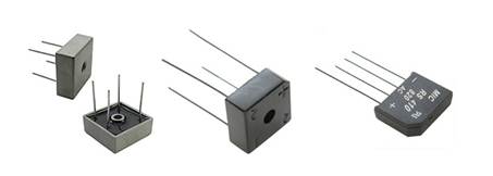
In addition to individual rectifier diodes, they are grouped according to application into one housing.
 Designation of the diode bridge
 For example, this is how it is depicted diode bridge for rectification of single-phase AC voltage. And lower appearance diode bridges and assemblies.

Another type of rectifier is Schottky diode– designed for operation in high-frequency circuits. Available both in discrete form and in assemblies. They can often be found in pulse blocks power supply, for example power supply for personal computer AT or ATX.
Typically, on Schottky assemblies, its pinout and internal connection circuit are indicated on the case.

Specific diodes
We have already looked at the rectifier diode, let's take a look at Zener diode, which in Russian literature is called - zener diode.
 Zener diode designation (Zener diode)
 Outwardly, it looks like a regular diode - a black cylinder with a mark on one side. Often found in a low-power version - a small red glass cylinder with a black mark on the cathode.
It has an important property - voltage stabilization, therefore it is switched on parallel to the load in the opposite direction, i.e. The plus of the power supply is connected to the cathode, and the anode to the minus.
The next device is varicap, the principle of its operation is based on changing the value of the barrier capacitance, depending on the magnitude of the applied voltage. Used in receivers and in circuits where it is necessary to perform operations on the signal frequency. Designated as a diode combined with a capacitor.
 Varicap - designation on the diagram and appearance
 – the designation of which looks like a diode crossed across. In fact, this is true - it is a 3-transition, 4-layer semiconductor device. Due to its structure, it has the property of passing current when overcoming a certain voltage barrier.
For example, dinistors of 30V or so are often used in “energy-saving” lamps, to start an autogenerator, and other power supplies built according to such a circuit.
 Dinistor designation
 LEDs and optoelectronics
Since the diode emits light, the designation means LED there should be an indication of this feature, so two outgoing arrows were added to the usual diode.

In reality there are many different ways determine the polarity, there is more information about this below, for example, the pinout of the green LED.
Typically, an LED's pins are marked either with a mark or with legs of different lengths. The short leg is a minus.

Photodiode, the device is the opposite in action to the LED. It changes its conductivity state depending on the amount of light falling on its surface. Its designation:

Such devices are used in televisions, tape recorders and other equipment that is controlled by remote control. remote control in the infrared spectrum. Such a device can be made by cutting off the body of a conventional transistor.
Often used in light sensors, devices automatic switching on and turning off lighting circuits, for example:

Optoelectronics is a field that has become widespread in data transmission and communication and control devices. Thanks to its fast response and galvanic isolation capability, it ensures safety for the powered devices in the event of a high-voltage surge on the primary side. However, not in the form as indicated, but in the form of an optocoupler.

At the bottom of the diagram you see an optocoupler. The LED is turned on here by closing the power circuit using an optotransistor in the LED circuit. When you close the switch, current flows through the LED in the optocoupler, in the bottom square on the left. It lights up and the transistor, under the influence of the light flux, begins to pass current through LED1, marked green.
The same application is used in circuits feedback by current or voltage (to stabilize them) of many power supplies. The scope of application starts from chargers mobile phones and power supplies for LED strips, to powerful power supply systems.
There are a great variety of diodes, some of them are similar in their characteristics, some have completely unusual properties and applications, they are united by the presence of only two functional terminals.
You can find these elements in any electrical diagram, their importance and characteristics cannot be underestimated. The correct selection of a diode in the snubber circuit, for example, can significantly affect the efficiency and heat dissipation of power switches, and, accordingly, the durability of the power supply.
If there was anything unclear to you, leave comments and ask questions; in the following articles we will definitely reveal all the unclear questions and interesting points!
We very often use diodes in our circuits, but do you know how they work and what they are? Today, the “family” of diodes includes more than a dozen semiconductor devices called “diodes”. The diode is a small container with evacuated air, inside which there is a short distance The anode and the second electrode, the cathode, are located apart from each other, one of which has electrical conductivity of type p, and the other - n.
To imagine how a diode works, let’s take as an example the situation of inflating a wheel using a pump. Here we are working with a pump, air is pumped into the chamber through the nipple, but this air cannot escape back through the nipple. Essentially, air is the same electron in a diode; an electron has entered, but it is no longer possible to get back out. If the nipple suddenly fails, the wheel will deflate and there will be a breakdown of the diode. And if we imagine that our nipple is working properly, and if we press the nipple pin to release air from the chamber, and press as we want and for how long, this will be a controlled breakdown. From this we can conclude that the diode passes current only in one direction (it also passes in the opposite direction, but very small)
The internal resistance of a diode (open) is not a constant value; it depends on the forward voltage applied to the diode. The higher this voltage, the greater the forward current through the diode, the lower its throughput resistance. You can judge the resistance of a diode by the voltage drop across it and the current through it. So, for example, if a direct current Ipr flows through the diode. = 100 mA (0.1 A) and at the same time the voltage across it drops 1V, then (according to Ohm’s law) the forward resistance of the diode will be: R = 1 / 0.1 = 10 Ohms.
I’ll note right away that we won’t go into details and go deep, draw graphs, write formulas - we’ll look at everything superficially. In this article we will consider the types of diodes, namely LEDs, zener diodes, varicaps, Schottky diodes, etc.
Diodes
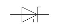
They are indicated on the diagrams like this:
The triangular part is the ANODE, and the dash is the CATHODE. The anode is a plus, the cathode is a minus. Diodes, for example, are used in power supplies to rectify alternating current; using a diode bridge, you can turn alternating current permanently, used for protection different devices from incorrect switching polarity, etc.
The diode bridge consists of 4 diodes that are connected in series, and two of these four diodes are connected back-to-back, look at the pictures below.

This is exactly how a diode bridge is designated, although in some circuits it is designated as an abbreviated version:

Conclusion ~ connected to a transformer, in the diagram it will look like this:

The diode bridge is designed to convert, more often they say, to rectify alternating current into direct current. This type of rectification is called full-wave rectification. The operating principle of a diode bridge is to pass the positive half-wave of alternating voltage by positive diodes and cut off the negative half-wave by negative diodes. Therefore, a slightly pulsating positive voltage with a constant value is formed at the output of the rectifier.

To prevent these pulsations, electrolytic capacitors are installed. after adding a capacitor, the voltage increases slightly, but let’s not get distracted, you can read about capacitors.

Diode bridges are used to power radio equipment, used in power supplies and chargers. As I already said, a diode bridge can be made up of four identical diodes, but ready-made diode bridges are also sold, they look like this:
Schottky diodes have a very low voltage drop and are faster than conventional diodes.

It is not recommended to install a regular diode instead of a Schottky diode; a regular diode can quickly fail. Such a diode is designated in the diagrams as follows:
Zener diode
The zener diode prevents the voltage from exceeding a certain threshold in a specific section of the circuit. Can perform both protective and restrictive functions; they only work in circuits direct current. When connecting, the polarity must be observed. Zener diodes of the same type can be connected in series to increase the stabilized voltage or form a voltage divider.

Zener diodes in the diagrams are designated as follows:

The main parameter of zener diodes is the stabilization voltage; zener diodes have different stabilization voltages, for example 3V, 5V, 8.2V, 12V, 18V, etc.
A varicap (or capacitive diode) changes its resistance depending on the voltage applied to it. It is used as a controlled variable capacitor, for example, for tuning high-frequency oscillatory circuits.


The thyristor has two stable states: 1) closed, that is, a state of low conductivity, 2) open, that is, a state of high conductivity. In other words, it is capable of transitioning from a closed state to an open state under the influence of a signal.

The thyristor has three outputs, in addition to the Anode and Cathode, there is also a control electrode - used to switch the thyristor to the on state. Modern imported thyristors are also produced in TO-220 and TO-92 cases.
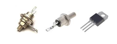
Thyristors are often used in circuits to regulate power, to smoothly start motors or turn on light bulbs. Thyristors allow you to control large currents. For some types of thyristors, the maximum forward current reaches 5000 A or more, and the voltage value in the closed state is up to 5 kV. Powerful power thyristors of the type T143 (500-16) are used in control cabinets for electric motors and frequency converters.

Triac
A triac is used in systems powered by alternating voltage; it can be thought of as two thyristors that are connected back-to-back. The triac allows current to flow in both directions.

Light-emitting diode
An LED emits light when electric current is passed through it. LEDs are used in instrument display devices, electronic components (optocouplers), cell phones for display and keyboard backlighting, powerful LEDs used as a light source in lanterns, etc. LEDs come in different colors, RGB, etc.

Designation on the diagrams:

Infrared diode
Infrared LEDs (abbreviated IR diodes) emit light in the infrared range. The areas of application of infrared LEDs are optical instrumentation, remote control devices, optocoupler switching devices, and wireless communication lines. IR diodes are designated in the same way as LEDs.

Infrared diodes emit light outside the visible range, the glow of an IR diode can be seen and viewed, for example, through a camera cell phone, these diodes are also used in CCTV cameras, especially on street cameras so that the picture is visible in the dark.
Photodiode
A photodiode converts light falling on its photosensitive region into electric current, and is used in converting light into an electrical signal.

Photo diodes (as well as photoresistors, phototransistors) can be compared with solar panels. They are designated as follows in the diagrams.
Diode- This is an element that has different conductivity. This property is used in various electrical and electronic circuits. Based on it, devices are created that are used in various fields.
Types of diodes: vacuum and semiconductor. The latter type is currently used in the vast majority of cases. It will never be superfluous to know how a diode works, what it is needed for, how it is indicated on the diagram, what types of diodes exist, the use of different types of diodes.
Electrovacuum diodes
Devices of this type are made in the form of electron tubes. The lamp looks like a glass container with two electrodes placed inside it. One of them is an anode, the other is a cathode. They are in a vacuum. Structurally, the anode is made in the form of a thin-walled cylinder. The cathode is located inside. It usually has a cylindrical shape. An insulated filament is laid inside the cathode. All elements have leads that are connected to the pins (legs) of the lamp. The legs of the lamp are brought out.
Principle of operation
When an electric current passes through the spiral, it heats up and heats the cathode inside which it is located. From the surface of a heated cathode, electrons that leave it, without an additional accelerating field, accumulate in the immediate vicinity of it. Some of them are then returned to the cathode.
When a positive voltage is applied to the anode, electrons emitted by the cathode rush towards it, creating an anode electron current.
The cathode has a limit on electron emission. When this limit is reached, the anode current stabilizes. If a small negative voltage is applied to the anode relative to the cathode, the electrons will stop moving.
The cathode material from which it is made has a high degree of emission.
Current-voltage characteristic (CVC)
The current-voltage characteristic of diodes of this type graphically shows the dependence of the anode current on the forward voltage applied to the cathode and anode terminals. It consists of three sections:
- Slow nonlinear increase in current;
- Working part characteristics;
- Anode current saturation region.
The nonlinear section begins after the anodic current cutoff region. Its nonlinearity is associated with the small positive potential of the cathode, which electrons left when it was heated by the filament.
The active area defines itself almost vertical line. It characterizes the dependence of the anode current on increasing voltage.
The saturation section is a line of constant anode current with increasing voltage between the lamp electrodes. Electron tube in this area can be compared to an electric current conductor. The cathode emission reached its highest value.
Semiconductor diodes
 The property of a p-n junction to pass electric current in one direction has found application in the creation of devices of this type. Direct connection is the supply of a negative potential to the n-region of the transition, in relation to the p-region, the potential of which is positive. When turned on in this way, the device is in the open state. When the polarity of the applied voltage changes, it will be in a locked state, and no current will pass through it.
Diodes can be classified according to their purpose, manufacturing features, and the type of material used in its manufacture.
Basically, silicon or germanium wafers, which have n-type electrical conductivity, are used for the manufacture of semiconductor devices. They contain an excess of negatively charged electrons.
Applying different technologies manufacturing, you can get point or plate diodes at the output.
When making point devices, a pointed conductor (needle) is welded to an n-type plate. A certain impurity is applied to its surface. For germanium wafers, the needle contains indium; for silicon wafers, the needle is coated with aluminum. In both cases, a p-n junction region is created. Its shape resembles a hemisphere (point).
For planar devices, the diffusion or fusion method is used. The area of transitions obtained by this method varies widely. The further purpose of the product depends on its size. Wires are soldered to the p-n junction areas, which are used in the form of leads from the body of the finished product when installing various electrical circuits.
In the diagrams, semiconductor diodes are designated in the form of an equilateral triangle, to the upper corner of which is attached a vertical line parallel to its base. The terminal of the line is called the cathode, and the terminal of the base of the triangle is the anode.
Direct connection is such a connection in which the positive pole of the power source is connected to the anode. When turned back on, the “plus” of the source is connected to the cathode.
Volt-ampere characteristics
The current-voltage characteristic determines the dependence of the current flowing through a semiconductor element on the magnitude and polarity of the voltage applied to its terminals.
In the region of forward voltages, three regions are distinguished: a small forward current and a forward operating current through the diode. The transition from one region to another occurs when the direct voltage reaches the conductivity threshold. This value is on the order of 0.3 volts for germanium diodes and 0.7 volts for silicon-based diodes.
When a reverse voltage is applied to the terminals of a diode, the current through it is very small and is called reverse current or leakage current. This dependence is observed up to a certain value of the reverse voltage. It is called breakdown voltage. When it is exceeded, the reverse current increases like an avalanche.
Parameter Limits
For semiconductor diodes, there are parameter values that cannot be exceeded. These include:
- Maximum forward current;
- Maximum reverse breakdown voltage;
- Maximum power dissipation.
A semiconductor element can withstand a limited amount of forward current through it. If it is exceeded, overheating occurs p-n junction and its failure. Planar power devices have the greatest margin for this parameter. The magnitude of the direct current through them can reach tens of amperes.
Exceeding the maximum breakdown voltage can turn a diode, which has unidirectional properties, into an ordinary conductor of electric current. The breakdown can be irreversible and varies widely, depending on the specific device used.
Power- this is a quantity that directly depends on the current and voltage that is applied to the diode terminals. Like exceeding the maximum forward current, exceeding the maximum dissipation power leads to irreversible consequences. The diode simply burns out and ceases to fulfill its purpose. To prevent such a situation, power devices install devices on radiators, which remove (dissipate) excess heat into the environment.
Types of semiconductor diodes
The property of a diode to pass current in the forward direction and not pass it in the reverse direction has found application in electrical engineering and radio engineering. Special types of diodes have also been developed to perform a narrow range of tasks.
Rectifiers and their properties
 Their use is based on the rectifying properties of these devices. They are used to obtain a constant voltage by rectifying the input alternating signal.
A single rectifier diode allows you to obtain a pulsating voltage of positive polarity at its output. Using a combination of these, a wave-like output voltage waveform can be obtained. When using additional elements such as electrolytic capacitors in rectifier circuits large capacity and inductors with electromagnetic cores (chokes), the output of the device can be obtained constant pressure, reminiscent of the voltage of a galvanic battery, so necessary for the operation of most consumer equipment.
Semiconductor Zener diodes
These diodes have a I-V characteristic with a high steepness reverse branch. That is, by applying a voltage whose polarity is reversed to the zener diode terminals, you can use limiting resistors to enter it into the avalanche-controlled breakdown mode. The voltage at the point of avalanche breakdown has a constant value with a significant change in the current through the zener diode, the value of which is limited depending on the device used in the circuit. This results in the effect of stabilizing the output voltage at the desired level.
Technological operations in the manufacture of zener diodes achieve different values of breakdown voltage (stabilization voltage). The range of these voltages is (3−15) volts. The specific value depends on the selected device from a large family of zener diodes.
Operating principle of detectors
To detect high-frequency signals, diodes made using point technology are used. The detector's job is to limit one half of the modulated signal. This allows you to subsequently use a high-pass filter to leave only the modulating signal at the output of the device. It contains low frequency audio information. This method is used in radio receivers that receive an amplitude modulated signal.
Features of LEDs
These diodes are characterized by the fact that when forward current flows through them, the crystal emits a stream of photons, which are a source of light. Depending on the type of crystal used in the LED, the light spectrum can be either in the range visible to the human eye or in the invisible range. Invisible light is infrared or ultraviolet radiation.
When choosing these elements, it is necessary to imagine the goal that needs to be achieved. The main characteristics of LEDs include:
- Power consumption;
- Rated voltage;
- Consumption current.
The current consumption of the LED used for indication in widely used devices is no more than 20 mA. At this current, the LED glow is optimal. The onset of luminescence begins at a current exceeding 3 mA.
The rated voltage is determined internal resistance transition, which is a variable quantity. As the current through the LED increases, the resistance gradually decreases. The voltage of the power source used to power the LED must be used no less than the voltage specified in its data sheet.
Power consumption is a value that depends on the current consumption and the rated voltage. It increases with increasing quantities that determine it. It should be taken into account that powerful light diodes can contain 2 or even 4 crystals.
LEDs have undeniable advantages over other lighting devices. They can be listed for a long time. The main ones are:
- High efficiency;
- Great durability;
- High level of safety due to low supply voltages.
The disadvantage of their operation is the need for an additional stabilized DC power source, and this increases the cost.
We all know very well what a semiconductor diode is, but few of us know about the principle of operation of a diode. Today, especially for beginners, I will explain the principle of its operation. As is known, a diode passes current well on one side, but very poorly on the opposite direction. The diode has two terminals - anode and cathode. Not a single electronic device can do without the use of diodes. The diode is used to rectify alternating current, with the help of a diode bridge which consists of four diodes, you can turn alternating current into direct current, or using six diodes you can turn three-phase voltage into single-phase, diodes are used in a variety of power supplies, in audio-video devices, almost everywhere . Here you can see photos of some.
You can notice a drop in the diode output entry level voltage by 0.5-0.7 volts. For lower voltage power supply devices, a Schottky diode is used; on such a diode the smallest voltage drop is observed - about 0.1V. Schottky diodes are mainly used in radio transmitting and receiving devices and in other devices operating mainly at high frequencies. The operating principle of a diode is quite simple at first glance: a diode is a semiconductor device with one-way conductivity of electric current.

The diode terminal connected to the positive pole of the power source is called the anode, and the negative terminal is called the cathode. The diode crystal is mainly made of germanium or silicon, one region of which has n-type electrical conductivity, that is, a hole region, which contains an artificially created lack of electrons, the other - n-type conductivity, that is, contains an excess of electrons, the boundary between them is called a n-n junction , n is the first letter of the word positive in Latin, n is the first letter of the word negative. If a positive voltage is applied to the anode of the diode, and a negative voltage is applied to the cathode, then the diode will pass current, this is called direct connection, in this position the diode is open, if reverse is applied, the diode will not pass current, in this position the diode is closed, this is called reverse connection .

The reverse resistance of the diode is very high and in circuits it is considered a dielectric (insulator). Showcase your work semiconductor diode can be assembled simple diagram which consists of a power source, a load (for example, an incandescent lamp or a low-power electric motor) and the semiconductor diode itself. We connect all the components of the circuit in series, we supply plus from the power source to the anode of the diode, in series to the diode, that is, we connect one end of the light bulb to the cathode of the diode, and connect the other end of the same lamp to the minus of the power source. We observe the glow of the lamp, now we turn the diode over, the lamp will no longer glow because the diode is connected back, the transition is closed. I hope this will help you in some way in the future, newbies - A. Kasyan (AKA).
