Frequency of testing voltage indicators above 1000 V. Voltage indicators. Order testing of high voltage indicators at a discount
If you need specialized testing of protective equipment in electrical installations, testing of high-voltage indicators, or any other electrical laboratory services at an affordable price, contact LabTestEnergo. We are ready to provide the services of competent specialists with at least 10 years of experience, select a convenient time for you and perform urgent checks during the day. Upon completion of the tests, you will receive official protocols reflecting the measurement results.

Why do pointer checking?
A voltage detector is an insulation device that is used for the purpose of detecting high voltage (up to and above 1000 V). They are used before carrying out repair or service work. The legislation also regulates the mandatory use of indicators in the process of phasing electrical equipment.
The pointer consists of a working part, insulating material and a handle. There are several types of indicators, which means that during operation and testing, it is necessary to comply with the requirements for a specific type. It is allowed to use pointers that do not have mechanical damage and defects.
Carrying out periodic tests ensures safe operation of electrical equipment. Employees of the LabTestEnergo electrical laboratory use modern equipment and devices for this purpose. During the tests, the insulation condition and indication voltage are checked. It is recommended to carry out such checks once every 12 months.
Order testing of high voltage indicators at a discount
LabTestEnergo is a leading specialist in the field of electrical measurements and testing of electrical equipment in Moscow and Moscow Region. We work under an official contract, observing norms and standards, we are ready to perform urgent work, provide you with a discount and a documentary conclusion with measurement results.

If you decide to enter into a contract for or tests in electrical installations, the inspection is carried out free of charge. To clarify the details of the promotion and calculate the preliminary cost of the work, call us at +7 495 777 1076. Our manager will answer all questions and help you arrange a convenient date and time for the work.
| Type of protection | Test cost 1 unit, | Periodicity | |
| Duration - up to 4 days | Urgent tests (1 day) | ||
| Voltage indicator 2-pole up to 1 kV | 245 | 345 | Once every 12 months. |
| Voltage indicator 1-pole up to 1 kV | 245 | 345 | Once every 12 months. |
| Voltage indicator for phasing up to 10 kV | 245 | 345 | Once every 12 months. |
| High voltage indicator UVN-80, etc. | 245 | 345 | Once every 12 months. |
* For details of the promotion, please call
SO 153-34.03.603-2003 p.Appendix 7Appendix 7
Norms and terms of operational electrical testing of protective equipment
| Test frequency | |||||
| Voltage indicators up to 1000 V | Once every 12 months. | ||||
| - housing insulation | Up to 0.5 | - | |||
| Above 0.5 to 1 | - | ||||
| - high voltage test: | |||||
| - single-pole | Up to 1 | 1.1 Urab. naib | - | ||
| - bipolar | Up to 1 | 1.1 Urab. naib | - | ||
| - checking the current through the pointer: | |||||
| single pole | Up to 1 | Uwork naib | - | 0,6 | |
| bipolar*2 | Up to 1 | Uwork naib | - | ||
| - voltage | Up to 1 | Not higher than 0.05 | - | - | |
| indications |
How often should electrical tests be carried out on voltage indicators to check phase alignment?
| Once every 6 months |
| Once every 12 months |
| Once every 24 months |
| Once every 36 months |
SO 153-34.03.603-2003 p.Appendix 7
| Name of the protective equipment | Voltage of electrical installations, kV | Test voltage, kV | Test duration, min. | Current flowing through the product, mA, no more | Test frequency |
| Voltage indicators for checking phase coincidence: | Once every 12 months. | ||||
| - insulating | To 10 | - | |||
| Part | Above 10 to 20 | - | |||
| - | |||||
| - | |||||
| - working part | To 10 | - | |||
| - | |||||
| - | |||||
| - | |||||
| - | |||||
| - indication voltage: | |||||
| according to the consonantal pattern | Not less than 7.6 | - | - | ||
| inclusion | Not less than 12.7 | - | - | ||
| At least 20 | - | - | |||
| At least 28 | - | - | |||
| At least 40 | - | - | |||
| At least 100 | - | - | |||
| according to the scheme | Not higher than 1.5 | - | - | ||
| oncoming | Not higher than 2.5 | - | - | ||
| inclusion | Not higher than 3.5 | - | - | ||
| Not higher than 5 | - | - | |||
| No higher than 17 | - | - | |||
| Not higher than 50 | - | - | |||
| - connecting | Up to 20 | - | - | ||
| the wire | 35-110 | - | - |
How often should electrical tests be carried out on clamp meters?
How often should electrical tests be carried out on cable piercing devices?
TICKET 9
How often should electrical tests of dielectric gloves be carried out?
How often should electrical tests be carried out on dielectric boats?
How often should electrical tests be carried out on dielectric pads?
| Once every 6 months |
| Once every 12 months |
| Once every 24 months |
| Once every 36 months |
SO 153-34.03.603-2003 p. Appendix 7 Norms and terms of operational electrical tests of protective equipment
| Name of the protective equipment | Voltage of electrical installations, kV | Test voltage, kV | Test duration, min. | Current flowing through the product, mA, no more | Test frequency |
| Insulating pads: | Once every 24 months | ||||
| - hard | Up to 0.5 | - | |||
| Above 0.5 to 1 | - | ||||
| Above 1 to 10 | - | ||||
| - | |||||
| - | |||||
| - flexible from | Up to 0.5 | ||||
| polymer materials | Above 0.5 to 1 |
Which document indicates the number of the test report for protective equipment?
SO 153-34.03.603-2003 p. Appendix 1
What duration of application of the test voltage is established for flexible insulating pads for work under voltage in electrical installations up to 1000 V?
| 5 minutes |
| 1 minute |
| 3 minutes |
Voltage indicators are portable devices designed to check the presence or absence of voltage on live parts. Such a check is necessary, for example, when working directly on disconnected live parts, when monitoring the serviceability of electrical installations, finding faults in an electrical installation, checking electrical diagram and so on.
In all these cases, it is necessary to establish only the presence or absence of voltage, but not its value, which, as a rule, is known.
All indicators have a light signal, the lighting of which indicates the presence of voltage on the part being tested or between the parts being tested. Indicators are available for electrical installations up to 1000 V and above.
Indicators intended for electrical installations up to 1000 V are divided into two-pole and single-pole.
Bipolar indicators require touching two parts of the electrical installation, between which it is necessary to determine the presence or absence of voltage. The principle of their operation is the glow of a neon light bulb or incandescent lamp (with a power of no more than 10 W) when a current flows through it, caused by the potential difference between the two parts of the electrical installation that the pointer touches. Consuming a small current - from fractions to several milliamps, the lamp provides a stable and clear light signal, emitting orange-red light.
After the discharge occurs, the current in the lamp circuit gradually increases, i.e. The resistance of the lamp seems to decrease, which ultimately leads to lamp failure. To limit the current to a normal value, a resistor is connected in series with the lamp.

Bipolar indicators can be used in both AC and DC installations. However, with alternating current, the metal parts of the indicator - lamp base, wire, probe can create a capacitance relative to the ground or other phases of the electrical installation, sufficient so that when only one probe touches the phase, the indicator with a neon bulb glows. To eliminate this phenomenon, the circuit is supplemented with a shunt resistor that shunts the neon light bulb and has a resistance equal to the additional resistor.
 Single-pole indicators require touching only one - the live part being tested. Communication with the ground is ensured through the human body, which creates contact with the pointer circuit with the finger of the hand. In this case, the current does not exceed 0.3 mA.
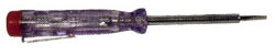
Single-pole indicators are usually made in the form of an automatic pen, in the body of which, made of insulating material and having an inspection hole, a signal light and a resistor are placed; At the lower end of the housing there is a metal probe, and at the upper end there is a flat metal contact, which the operator touches with his finger.
The single-pole indicator can only be used in installations alternating current, since with constant current its lamp does not light even in the presence of voltage. It is recommended to be used when checking secondary switching circuits, determining the phase wire in electric meters, lamp sockets, switches, fuses, etc.
When using voltage indicators up to 1000 V, you can do without protective equipment.
Safety regulations prohibit the use of a so-called test lamp instead of a voltage indicator - an incandescent lamp screwed into a socket charged with two short wires. This prohibition is due to the fact that if the lamp is accidentally turned on at a voltage higher than it is designed for, or if it hits a hard object, its bulb may explode and, as a result, injure the operator.
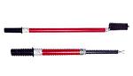
Indicators for electrical installations with voltages above 1000 V, also called high voltage indicators (HVN), operate on the principle of a neon light bulb glowing when a capacitive current flows through it, i.e. charging current of a capacitor connected in series with the light bulb. These indicators are suitable only for alternating current installations and they need to be brought closer to only one phase.
The designs of pointers are different, but UVNs always have three main parts: a working part, consisting of a housing, a signal lamp, a capacitor, etc., an insulating part, which ensures isolation of the operator from live parts and is made of insulating materials, and a handle designed to hold the pointer.
 When using UVN it is necessary to use dielectric gloves. Each time before using the UVN, it is necessary to carry out an external inspection of it to ensure that there is no external damage and to check the serviceability of its operation, i.e. ability to signal.
This check is carried out by bringing the pointer probe closer to live parts of the electrical installation that are known to be energized. Serviceability can be checked using special high-voltage sources, as well as using a megohmmeter and, finally, by bringing the indicator probe closer to the spark plug of a running car or motorcycle engine.
It is forbidden to ground the indicators, since they provide a fairly clear signal even without grounding, and besides, the grounding wire, if it touches live parts, can cause an accident.
In certain situations, when the capacity of the indicator relative to grounded objects turns out to be very small (for example, when working on wooden supports of overhead power lines), the voltage indicator must be grounded.
According to ch. 3.6. PTEEP “Guidelines for testing electrical equipment and devices of electrical installations of Consumers”, the timing of tests and measurements of parameters of electrical equipment of electrical installations is determined by the technical manager of the Consumer on the basis of Appendix 3 of the Rules, taking into account the recommendations of factory instructions, the state of electrical installations and local conditions. The frequency of tests indicated for certain types of electrical equipment is recommended and can be changed by the decision of the technical manager of the Consumer.
The acceptance test standards must comply with the requirements of Section 1 “General Rules” of Chapter 1.8. “Acceptance Test Standards” of Electrical Installation Rules (seventh edition).
In accordance with PTEEP (Appendix 3), measuring the insulation resistance of elements electrical networks are carried out within the following time frames:
electrical wiring, including lighting networks, in especially hazardous rooms and outdoor installations once a year, in other cases 1 time every 3 years;
cranes and elevators once a year;
stationary electric stoves once a year when the stove is hot.
In other cases, tests and measurements are carried out at intervals determined in the system of scheduled preventive maintenance (PPR), approved by the technical manager of the Consumer (clause 3.6.2. PTEEP).
For example, for healthcare institutions, according to intra-industry guidance documents, the following testing periods are defined:
checking the condition of the elements of the grounding device in the first year of operation, then at least once every three years;
checking the continuity of the circuit between the ground electrode and the grounded electromedical equipment at least once a year, as well as when rearranging electromedical equipment;
resistance of the grounding device at least once a year;
checking the impedance of the phase-zero loop when accepting the network for operation and periodically at least once every five years.
The frequency of preventive tests of explosion-proof electrical equipment is established by the person responsible for the electrical equipment of the Consumer, taking into account local conditions. It should be no less than specified in the chapters of PTEEP related to the operation of general-purpose electrical installations.
For electrical installations in explosive zones with voltages up to 1000 V with a solidly grounded neutral (TN systems), during major, current repairs and between-repairs tests, but at least once every 2 years, the total resistance of the phase-zero loop of electrical receivers related to this electrical installation and connected to each assembly, cabinet, etc., and check the short circuit current multiplicity, ensuring reliable operation of protective devices.
Unscheduled measurements should be carried out in the event of failure of electrical installation protection devices. After each rearrangement of electrical equipment, before turning it on, it is necessary to check its connection to the grounding device, and in a network with a voltage of up to 1000 V with a solidly grounded neutral, in addition, the resistance of the phase-zero loop.
The specific timing of tests and measurements of parameters of electrical equipment of electrical installations during major repairs (K), during routine repairs (T) and during between-repair tests and measurements (preventive tests) performed to assess the condition of electrical equipment without taking it out for repairs (M) is determined by the technical manager of the Consumer , based on PTEEP and various intersectoral guidance documents.
Below is a table corresponding to Appendix 3 of PTEEP and other NTD.
| № n\n |
Equipment identification | Type of equipment testing | Periodicity | Scope of preventative testing | Note | NTD |
|---|---|---|---|---|---|---|
| 1 | Oil-filled bushings | - | a) measurement of insulation resistance; (9.1) b) measurement tg of the dielectric loss angle; (9.2) c) testing with increased power frequency voltage; (9.3) d) transformer oil test (9.5) |
- | PTEEP Appendix 3 clause 9 |
|
| M (overhaul tests) | Once every 4 years | P.P. A); G) | - | |||
| K (during major repairs) | Once every 8 years | P.P. A); b); V); | - | |||
| 2 | Overhead power lines | P (before commissioning) | - | a) control of insulators; (7.8) b) measuring the resistance of supports and cables, as well as repeated grounding of the neutral wire; (7.10) c) checking the operation of line protection up to 1000 V with a grounded neutral |
- | PTEEP Appendix 3 clause 7 |
| M (overhaul tests) | Once every 6 years | P.P. A); b); | - | |||
| 3 | Oil and electromagnetic switches | P (before commissioning) | - | a) measurement of insulation resistance; (10.1) (10.2) c) testing of bushings (10.3) d) resistance measurement DC; (10.5) e) checking the operation of the free release mechanism; (10.8) f) checking the drive operation at low voltage; (10.10) g) test by repeated switching on and off (10.11) h) testing transformer oil; (10.12) |
- | PTEEP Appendix 3 clause 10 |
| M (overhaul tests) | Once every 4 yearsP.P. a), d), e), h) | - | ||||
| K (during major repairs) | Once every 8 years | P.P. a), b), c), d), e), f), g), h) | - | |||
| 4 | Air switches | - | a) measurement of insulation resistance; (11.1) b) testing with increased power frequency voltage; (11.2) c) DC resistance measurement; (11.3) d) checking the operation of the drive at low voltage; (11.4) e) checking the characteristics of the switch (11.5) f) test by repeated switching on and off (11.6) g) testing voltage divider capacitors (11.7) |
- | PTEEP Appendix 3 clause 11 |
|
| M (overhaul tests) | Once every 4 years | P.P. a), c), d), e) | - | |||
| K (during major repairs) | Once every 8 years | P.P. a), b), c), d), e), f), g) | - | |||
| 5 | SF6 gas switches 110 kV | P (before commissioning) | - | a) measurement of insulation resistance; (12.1) b) insulation tests with increased power frequency voltage; (12.2) c) DC resistance measurement; (12.3) d) checking the minimum operating voltage of switches (12.4) e) testing voltage divider capacitors (12.5) g) tests of built-in current transformers (12.9) |
- | PTEEP Appendix 3 clause 1 2 |
| M (overhaul tests) | Once every 4 years | P.P. a), b), c) g) | - | |||
| K (during major repairs) | Once every 8 years | P.P. a), b), c), d), e), g) | - | |||
| 6 | Vacuum switches 10 kV | P (before commissioning) | - | a) measurement of insulation resistance; (13.1) b) testing with increased power frequency voltage; (13.2) c) checking the minimum operating voltage of switches (13.3) d) tests by repeated sampling (13.4) e) checking the characteristics of the switch (13.5) |
- | PTEEP Appendix 3 clause 13 |
| M (overhaul tests) | Once every 5 years | P.P. A) | First test after 2 years | |||
| K (during major repairs) | Once every 10 years | P.P. a B C D E) | ||||
| 7 | Load switches | P (before commissioning) | - | a) measurement of insulation resistance; (14.1) b) testing with increased power frequency voltage; (14.2) c) DC resistance measurement (14.3) d) determining the degree of wear of arc extinguishing liners; (14.4) e) determination of the degree of contact burning; (14.5) f) checking the operation of the free release mechanism; (14.6) g) checking the drive operation at low voltage; (14.7) h) test by repeated switching on and off (14.8) |
- | PTEEP Appendix 3 clause 14 |
| M (overhaul tests) | Once every 4 years | P.P. A) | - | |||
| K (during major repairs) | Once every 8 years | - | ||||
| 7.1 | Automatic switches | P (before commissioning) | - | a) insulation resistance measurement b) testing with increased power frequency voltage; c) determining the characteristics of the switch d) determining the degree of wear of arc extinguishing liners; e) determination of the degree of contact burning; f) checking the operation of the free release mechanism; g) checking the drive operation at low voltage; h) test by repeated switching on and off |
- | - |
| - | K (during major repairs) | Once every 8 years | P.P. a), b), c), d), e), f), g), h) | -- | ||
| 8 | Grounding devices | a) checking the connections of grounding conductors with grounded elements; (26.1) b) measuring the resistance of grounding devices; (26.4) c) total resistance of the “PHASE-ZERO” loop |
Point c) in installations up to 1000 V at least once every 6 years | PTEEP Appendix 3 clause 26 |
||
| M (overhaul tests) | Once every 12 years | P.P. A); b) | - | - | ||
| Once every 6 years | P. c) | - | - | |||
| Once every 12 years | P.P. a B C) | - | - | |||
| 9 | Lightning protection devices | - | Once a year before a thunderstorm | a) measuring the resistance of grounding devices; | - | - |
| 10 | PROTECTIVE EQUIPMENT | - | - | a) high voltage tests | - | Rules for the use and testing of protective equipment Appendix No. 5 |
| 10.1 | Dielectric boots | M (overhaul tests) | Once every 3 years | P. a) | - | |
| Dielectric galoshes | M (overhaul tests) | 1 time per year | P. a) | - | ||
| Insulating pliers | M (overhaul tests) | 1 time every 2 years | P. a) | - | ||
| Insulating hoods | M (overhaul tests) | 1 time per year | P. a) | - | ||
| Insulating pads | M (overhaul tests) | 1 time every 2 years | P. a) | - | ||
| Rubber gloves (dielectric) | M (overhaul tests) | Once every 6 months | P. a) | - | ||
| UVN non-contact type | M (overhaul tests) | 1 time every 2 years | P. a) | - | ||
| UVN with gas-discharge lamp | M (overhaul tests) | 1 time per year | P. a) | - | ||
| Voltage indicators up to 1000 V | M (overhaul tests) | 1 time per year | P. a) | - | ||
| Voltage indicators for checking phase coincidence | M (overhaul tests) | 1 time per year | P. a) | - | ||
| 10.11 | Cable damage indicator (light signal) | M (overhaul tests) | 1 time per year | P. a) | - | - |
| 10.12 | Cable piercing device | M (overhaul tests) | 1 time per year | P. a) | - | |
| 10.13 | Insulating rods | M (overhaul tests) | 1 time every 2 years | P. a) | - | |
| 10.14 | Measuring rods | M (overhaul tests) | 1 time per year | P. a) | - | |
| 10.15 | Clamp meter | M (overhaul tests) | 1 time every 2 years | P. a) | - | |
| 10.16 | Other protective equipment, isolating devices for repair work under voltage in electrical installations 100 kV and above | M (overhaul tests) | 1 time per year | P. a) | - | |
| 10.17 | Suspension and support insulators | P (before commissioning) | - | b) high voltage tests; (8.2) |
- | PTEEP Appendix 3 clause 8 |
| K (during major repairs) | Once every 8 years | P.P. a), b) | - | |||
| 10.18 | Portable electrified tools and safety step-down transformers | P (before commissioning) | - | a) measurement of insulation resistance; (28.1) b) high voltage insulation test (28.2) | - | PTEEP Appendix 3 clause 28 |
| M (overhaul tests) | Once every 6 months | P. a) with checking idle speed (if possible) | Tool | |||
| 1 time per year | P. b) | Transformers | ||||
| K (during major repairs) | As needed | P.P. A); b) | - | |||
| 10.19 | Test installations: stationary, mobile, portable | P (before commissioning) | - | a) measurement of insulation resistance; (27.1) b) high voltage test; (27.2) c) checking the serviceability of measuring devices and test installations; (27.3) d) checking the operation of blocking and grounding devices, signaling devices (27.4) | - | PTEEP Appendix 3 clause 27 |
| M (overhaul tests) | 1 time per month | P. d) | - | |||
| Once every 6 years for stationary installations, once every 2 years for other installations | P.P. A); b); V); G) | - | ||||
| 11 | Cable lines (power) | P (before commissioning) | - | a) determining the integrity of the cable cores (6.1) b) measurement of insulation resistance; (6.2) c) tests with increased rectified voltage; (6.3) |
- | PTEEP Appendix 3 clause 6 |
| M (overhaul tests) | Once every 3 years | P.P. A); b); V) | - | |||
| K (during major repairs) | Once every 6 years and in case of cable breakdown | P.P. A); b); V) | - | |||
| 12 | Complete distribution devices(KRU and KRUN) | P (before commissioning) | - | a) measurement of insulation resistance; (22.1) b) testing with increased power frequency voltage; (22.2) c) checking the alignment and fit of the moving contacts into the fixed ones (22.3) d) DC resistance measurement; (22.4) |
- | PTEEP Appendix 3 clause 22 |
| M (overhaul tests) | Once every 3 years | P.P. A); V) | - | |||
| K (during major repairs) | Once every 6 years | P.P. A); b); V); G) | - | |||
| 13 | Power capacitors | P (before commissioning) | a) check appearance and sizes; (4.1) b) measurement of insulation resistance; (4.2) c) testing with increased power frequency voltage; (4.3) d) measuring the capacity of an individual element; (4.4) e) measurement of tg dielectric loss angle; (4.5) |
- | PTEEP Appendix 3 clause 4 |
|
| T (during current repairs) | 1 time per year | P.P. A); b); G); | - | |||
| K (during major repairs) | Once every 8 years | P. P. a); b); V); G); d) | - | |||
| 14 | TRANSFORMER OIL | - | - | - | - | RD 34.45-51..300-97 "Volume and norms tests electro equipment" Section 25. |
| 14.1 | Power transformers | P (before commissioning) | - | a) measurement of breakdown voltage; b) measurement tg of the dielectric loss angle; |
Item b) for TR-ROV 220 kV | |
| M (overhaul tests) | Once every 3 years | P.P. A) | Item b) for TR-ROV 220 kV | |||
| When gas protection is triggered | P.P. a) and gas analysis | - | - | |||
| K (tests during major repairs) | In accordance with section 1 | P.P. A); b) | - | |||
| 14.2 | Instrument transformers | M (overhaul tests) | Once every 3 years | a) measurement of breakdown voltage; b) measurement tg of the dielectric loss angle; | - | |
| With increasing tg of winding insulation | P. b) | Item b) for TR-ROV current 220 kV | - | |||
| 14.3 | Oil switches | During major, current and unscheduled repairs with the number of limiting outages 7 and > | - | a) measurement of breakdown voltage | - | - |
| 14.4 | DC machines | P (before commissioning) | - | a) measurement of winding insulation resistance; b) testing with increased power frequency voltage; c) DC resistance measurement; d) checking the operation of the machine at idle speed |
- | PTEEP Appendix 3 clause 24 |
| T (during current repairs) | 1 time per year | P. a) | - | |||
| K (during major repairs) | 1 time every 2 years | P.P. A); b); V); G) | - | |||
| 15 | MEASURING TRANSFORMERS | - | - | - | - | |
| 15.1 | Current transformers | P (before commissioning) | - | a) measurement of winding insulation resistance; (20.1) b) measurement tg of the dielectric loss angle of the windings; (20.2) c) insulation test with increased voltage frequency 50 Hz; (20.3) d) reading magnetization characteristics; (20.4) e) checking the transformation ratio (20.5) f) measurement of winding resistance to direct current; (20.6) g) Transformer oil tests (20.7) |
- | PTEEP Appendix 3 clause 21 |
| Once every 6 years | P.P. A); b); V); G); d) | Point d) 1 time every 3 years | ||||
| K (during major repairs | As required and test results | P.P. A); b); V); G); d) | - | |||
| 16 | POWER TRANSFORMERS AND AUTOTRANSFORMERS | - | - | - | - | PTEEP Appendix 3 clause 2 |
| 16.1 | Main transformers PS | P (before commissioning) | - | a) measurement of winding insulation resistance; (2.2) b) measurement tg of the dielectric loss angle of winding insulation; (2.3) c) measurement of winding resistance to direct current; (2.5) d) checking the transformation ratio; (2.6) e) checking the winding connection group; (2.7) g) transformer oil testing; (2.13) h) measurement of current and losses; (2.8) i) insulation testing with increased applied voltage of industrial frequency; (2.4) j) testing transformers by switching on a push to the rated voltage; (2.14) k) thermal imaging examination; (2.21) l) assessment of the state of the switching device; (2.9) m) testing the tank for density; (2.10) o) checking indicator silica gel; n) phasing of transformers |
- | |
| M (overhaul tests) | 1 time every 2 years | P.P. A); b); V); and); O) | P. a) 1 time every 4 years | |||
| K (tests during major repairs) | Depending on the technical condition | P.P. A); b); V); G); d); and); h); And); To); l); m); n); O); P) | P.P. A); b); V); e); and); h); check before withdrawing to the cap. repair | |||
| 16.2 | Other transformers (10/0,4) | P (before commissioning) | - | |||
| M (overhaul tests) | Once every 4 years | P.P. A); V); m); O) | - | |||
| K (during major repairs) | As needed depending on the technical condition | P.P. A); V); G); d); and); h); And); To); m); O); P) | Points a); V); e); and); h); check before withdrawing to the cap. repair | |||
| 17 | Fuses, fuse-disconnectors | P (before commissioning) | - | a) test of supporting insulation with increased voltage (15.1) b) definition of integrity fuse links (15.2) c) measuring the direct current resistance of the current-carrying part of the exhaust fuse holder; (15.3) d) checking the fuse-disconnector by 5 times of switching on and off (15.6) |
- | PTEEP Appendix 3 clause 15 |
| K (during major repairs) | Once every 8 years | P.P. a B C D) | - | |||
| 18 | Valve arresters and surge arresters | P (before commissioning) | - | a) resistance measurement (17.1) b) measurement of conduction current of arrester elements; (17.3) c) measurement of breakdown voltage of arresters (17.6) |
- | PTEEP Appendix 3 clause 17 |
| M (overhaul tests) | Once a year (before a thunderstorm) | P.P. a), b) | - | |||
| K (during major repairs) | Once every 8 years | P.P. a B C) | - | |||
| 19 | Disconnectors, separators and short circuiters | P (before commissioning) | - | a) measurement of insulation resistance; (16.1) b) high voltage tests; (16.2) c) DC resistance measurement (16.3) d) check by turning on and off 5 times (16.5) e) determination of timing characteristics (16.6) e) checking the operation of the mechanical lock (16.7) |
- | PTEEP Appendix 3 clause 16 |
| K (tests during major repairs) | Once every 8 years | P.P. a B C D E F) | - | |||
| 20 | Prefabricated and connecting busbars, GRU and RU cells | P (before commissioning) | a) measurement of insulation resistance; (8.1) b) high voltage tests (8.2) |
- | PTEEP Appendix 3 clause 8 |
|
| K (during major repairs) | Once every 6 years | P.P. a), b) | - | |||
| 21 | AC motors | P (before commissioning) | - | a) measurement of the insulation resistance of the electric motor; (23.1) b) test with increased voltage frequency 50 Hz; (23.3) c) DC resistance measurement; (23.4) d) measuring the gaps between the steel of the rotor and stator; (23.5) e) checking the operation of the electric motor at idle speed; (23.7) f) checking the operation of the electric motor under load; (23.10) g) checking the operation of machine protection up to 1000 V with a power system with a grounded neutral |
- | PTEEP Appendix 3 clause 23 |
| M (overhaul tests) | Once every 3 years | P.P. A); b); and); V); d) | ||||
| K (tests during major repairs) | - | P.P. A); b); V); G); d); e); and) | ||||
| 22 | Electrical wiring up to 1000 V | P (before commissioning) | - | a) measurement of insulation resistance; (28.1) b) high voltage insulation test (28.2) c) measurement of the resistance of the phase-zero loop (28.4) |
- | PTEEP Appendix 3 clause 28 |
| T (tests during current repairs) | Once every 6 years | P.P. A) | ||||
| K (during major repairs) | 1 time 12 years | P.P. A); b) | ||||
| 23 | Measurement of loop resistance phase zero and insulation resistance of explosion-proof equipment 0.4 kV | P (before commissioning) | |
- | PTEEP Appendix 3 clause 28 |
|
| M (overhaul tests) | 1 time every 2 years | P.P. A); b) | - | |||
| K (tests during major repairs) | Once every 8 years | P.P. A); b) | - | |||
| 24 | Measurement of loop resistance phase zero and insulation resistance of standard equipment (non-explosion-proof) | P (before commissioning) | - | a) measurement of insulation resistance; (28.1) b) measurement of the resistance of the phase-zero loop (28.4) |
- | PTEEP Appendix 3 clause 28 |
| M (overhaul tests) | Once every 4 years | P.P. A); b) | - | |||
| K (tests during major repairs) | Once every 8 years | P.P. A); b) | - |
