Firmware mk. Mini PC firmware process. Anti-bounce
Microcontrollers for beginners. Video tutorial. We write the program into the microcontroller (we flash the chip)
________________________________________________________________________________________________________
First simplest program, which controls the voltage at the microcontroller pins. Programming in the CodeVisionAVR editor. Transferring the program to the microcontroller memory (chip firmware). download(36 MB)
Content
If video recording does not work, installflash player and check sound card, ordownload material (36 MB). If there is a green screen instead of a video, reinstall the flash player (just download latest version). If the video is jerky, pause it and let it load a little. Player for watching flash video on your home machine. Expand the video to full screen. If they write “Video not found”, “Video not found” - restart the video again.
CodeVisionAVR editor - official website
If the microcontroller is not flashed, then:
1) Don't fuss.
Put the design aside, rest, drink some tea and relax. Real designs rarely start working the first time - this is normal, especially for beginners (since there are too many unaccounted factors that the brain is not able to immediately comprehend).
Professional developers rework their designs several dozen times :)))
Interesting property of the brain: As Mark Twain said: “Don’t put off until tomorrow what you can put off until the day after tomorrow.” Sometimes you just can’t write a program, come up with an electronic circuit, etc. In this case, you don’t need to put in extra effort. Put the task into your subconscious and wait a couple of days. After a break, things often work out by themselves. And much faster and better than if you suffered for the same couple of days from morning to night.
2) After resting, carefully check again:
Nutrition - not lower than 4.5 volts, it is advisable to take from USB of that computer to which the programmer is connected (to eliminate possible equalizing currents). Check the voltage with a tester;
Are the wires from the computer to the programmer too long? Long wires cause interference and increase the likelihood of data transmission failure;
Maybe the cable inside is broken? Test all the wires with a tester.
Are the wires mixed up? MOSI, MISO, SCK, RESET GND, was it stuck in the right place?
Is the programmer configured correctly? Setting >> Programmer;
Project >> Configure >> C Compiler;
Have you specified the crystal type correctly? Tools >> Chip Programmer;
Didn't you touch the fuses? If you touched it, you will have to install external quartz.
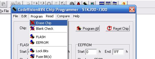
Did you clean the chip before flashing it? Tools >> Chip Programmer >> Program >> Erase Chip;
Sometimes completely cleaning the chip helps Tools >> Chip Programmer big kReset Chip button (equivalent to sending a pulse to the RESET pin);
Place it at the very bottom of the window Tools >> Chip Programmer three ticks Check Signature, Check erasure , Verify ;
Or vice versa - uncheck these boxes. Try this and that.
If all else fails, then order a new chip. A chip pulled out from somewhere may turn out to be burnt, or tuned to an external generator, or with burnt out pins, and the like.And sometimes in stores they sell defective ones, because... stored God knows where. Sometimes it is easier to buy a new chip than to think about what happened to the old one (but don’t throw it away; when you gain experience, restore it).
If you find it old computer- will try e do LPT programmer(What if they slipped a defective USB programmer?). There is nothing simpler than an LPT programmer; I did it on a dozen computers - it always started working right away and there were never any failures.
Don't forget before installation ground your hands a radiator, a faucet, or a solid steel structure (a fence, a bookcase), or buy an antistatic wristband or mat (static electricity from your hands can damage flimsy chips).
Finally, the most perverted way - try another computer. It happens that motherboards they glitch, the ports on them burn out, the wires come off the contacts, etc.
Learn microcontrollers not only from videos on this site. The brain needs variety. Read books, forums, Wikipedia, and other sites. Ask your fellow electronics engineers for advice. Practice and experiment on your own. Accumulate knowledge and experience.
How to flash an AVR microcontroller? This is exactly what we will do in this article.
What is “flashing” and “firmware”?
Let's first decide what the word means “flash”? I think you have often heard phrases such as “flash the phone”, “the firmware has crashed”, “the firmware is crooked” etc. What is it "firmware"?
Firmware is, roughly speaking, an operating system for small devices such as mobile phone, MP3 player, digital camera, etc. That is, it is a small program that controls this device. You can also often hear this: “I have a bug.” cellular telephone, we need it urgently “reflash“.
In this case, this means that you need to reinstall operating system to a mobile phone. Means, “flash MK” means uploading a program inside it that would control this MK, and the MK would already control some device. That is, in theory, MK is an intermediary between the program and some device that needs to be controlled;-)

Equipment for MK firmware
So, what do we need to flash the MK?
- The microcontroller itself.
- Computer with pre-installed software(BY).
- Programmer.
- Several jumpers.
- Bread board . I would recommend immediately buying a set for a beginner AVR player. This set is USB powered.
- Straight arms growing from the right place.
We have agreed to use the Atiny2313 MK in a DIP-20 package:

Preparing MK for firmware
In previous articles, we looked at the Gromov programmer. Its main disadvantage is that we need a COM port, which can hardly be found on a computer now, but there is a USB connector on every computer. Therefore, it was decided to buy the cheapest USB programmer for AVR MK. This programmer is called and it looks something like this

If you rummage around on Ali, you can find a very sweet price for such a programmer. For example, . You might even find it cheaper. If you buy from another seller, then carefully check that its inscriptions and radio elements were located exactly as in my photo. On average, its price at the time of writing is about 120 rubles. Such a programmer in a case will cost a little more.
Here's his rear view:

Its working connector looks something like this:

The programmer also comes with a cable

which at one end clings to the working connector of the programmer:

We will attach the other end of the cable to the MK.
If you look closely, you can find out which pin is the first in the connector. The arrow will point to the first pin of the connector:

Once you know where the first pin is located, you can easily determine the remaining pins:


So, our task is to connect the outputs of the MK to the outputs of the programmer.
To do this, we plug wires into the connector of the cable into the MOSI, RST, SCK, MISO, VTG (VCC), GND sockets. GND I took socket 10, you can use another one where GND is written. Total 6 jumper wires:

VTG (aka VCC) we hook it to the 20th leg of the MK
SCK(UCSK) we hook onto the 19th leg of the MK
MISO we hook it to the 18th leg of the MK
MOSI for 17 leg
GND for 10 leg
RST on the first leg
It should look something like this:

After plugging the programmer into the USB port of your PC for the first time, device Manager we will be given a new device:

Don’t be afraid, download the archive file, unpack it and point the path to it when installing the “firewood”. When the “firewood” is installed on the programmer, we will see something like this:

Everything is OK, the programmer is ready for battle.
In the same archive we find the folder “avrdudeprog”, open it, find it there executable file AVRDUDEPROG and launch it. That's what it is shell for flashing the MK using our programmer.
She looks like this. Don't forget to select our MK in the list.

In order to flash the MK, we need to select a file with the HEX extension. So here is my file. First thing I do is press the button “Erase everything”. What if someone has already used MK and some program is already loaded there? Therefore, before flashing the firmware, we erase the memory of the MK. If the “washing” was successful, the program will give us something like this:

Flashing MK AVR
Click on the file selection button:

Now select our file “Lesson 1.hex”. This is our program.

Now let's press the button "Programming"

After everything went well, something like this will be displayed:

But that is not all! As you remember, in the last article we set the frequency to 8 Megahertz. To avoid confusion, we now need to divide this frequency by 8. For this, there is a fuse that divides clock frequency exactly at 8. Put a marker on “straight fuses”, then put a tick on CKDIV.

After we have completed these two steps, click on the button "Programming":

Checking the MK in the hardware
Now we assemble our circuit, which was discussed in the previous article:

and enjoy the result:
December 2015
1. Advantages of the proposed method
Device circuits based on microcontrollers (MCUs) are usually distinguished by a combination of two difficult-to-combine qualities: maximum simplicity and high functionality. In addition, the functionality can be changed and expanded in the future without making any changes to the circuit - just by replacing the program (flashing). These features are explained by the fact that the creators of modern MKs tried to place on one chip everything that a developer might need electronic device- By at least as much as possible. As a result, there was a shift in emphasis from circuitry and installation to software. With the use of MK, there is now less need to “load” the circuit with parts, and there are fewer connections between components. This, of course, makes the circuit more attractive for repetition by both experienced and novice electronics engineers. But, as usual, you have to pay for everything. This, too, was not without its difficulties. If you buy a new MK, install it in a circuit correctly assembled from serviceable parts and apply power, then nothing will work - the device will not work. The microcontroller needs a program.
It would seem that everything is simple with this too - on the Internet you can find many schemes with free firmware. But here there is one catch: the firmware must somehow be “uploaded” into the microcontroller. For someone who has never done this before, such a task often becomes a problem and the main repulsive factor, often forcing them to abandon the delights of using MK and look for schemes based on “loose” and rigid logic. But everything is not as complicated as it might seem at first glance.
After analyzing publications on the Internet, you can see that this problem This problem is most often solved in one of two ways: buying a ready-made programmer or making a homemade one. At the same time, published diagrams homemade programmers very often unnecessarily complex - much more complex than is really necessary. Of course, if you plan to flash the MK every day, it is better to have a “cool” programmer. But if the need for such a procedure arises infrequently, from time to time, then you can do without a programmer altogether. No, of course, we are not talking about learning to do this with the power of thought. This means that by understanding how the programmer interacts with the microcontroller when writing and reading information in its programming mode, we can make do with available tools for a wider purpose. These tools will have to replace both the software and hardware parts of the programmer. The hardware must provide a physical connection to the MK microcircuit, the ability to apply logical levels to its inputs and read data from its outputs. The software part must ensure the operation of the algorithm that controls all the necessary processes. We also note that the quality of recording information in the MK does not depend on how “cool” your programmer is. There is no such thing as “better recorded” or “worse”. There are only two options: “registered” and “not registered”. This is explained by the fact that the recording process inside the crystal is directly controlled by the MK itself. You just need to provide it with high-quality power (no interference or ripple) and properly organize the interface. If the results of the test reading reveal no errors, then everything is in order - you can use the controller for its intended purpose.
In order to write a program into the MK without a programmer, we need a converter USB port-RS232TTL and as well as . The USB-RS232TTL converter allows you to use a USB port to create a COM port that differs from the “real” one only in that its inputs and outputs use TTL logical levels, that is, voltage in the range from 0 to 5 volts (you can read more in the article " "). In any case, such a converter is useful to have in your “household,” so if you don’t already have one, it’s definitely worth purchasing. As for the logical levels, in our case TTL is even an advantage over a regular COM port, because the inputs and outputs of such a port can be directly connected to any microcontroller powered by 5 V, including ATtiny and ATmega. But do not try to use a regular COM port - they use voltages in the range from -12 to +12 V (or -15...+15V). In this case, direct connection to the microcontroller is unacceptable!!!
The idea of creating a script for the Perpetuum M program, which implements the functions of the programmer, arose after reading a number of publications on the Internet offering certain solutions for MK firmware. In each case, serious deficiencies or excessive difficulties were discovered. Often I came across programmer circuits that contained a microcontroller, and at the same time, advice was given quite seriously like: “... and to program the microcontroller for this programmer we will need... that’s right - another programmer!” Next, it was suggested to go to a friend and look for paid service and so on. The quality of the software distributed on the network for these purposes was also not impressive - many problems were noticed both with functionality and with "cloudiness" user interface. It often takes a lot of time to understand how to use a program - it must be studied even to carry out the simplest actions. Another program can do something for a long time and diligently, but the user learns that nothing is being written to the MK only after the entire firmware has been completely completed and subsequent test reading. The following problem also occurs: the user tries to select his MK from the list of supported crystals, but it is not in the list. In this case, you will not be able to use the program - inclusion in the list of missing MKs, as a rule, is not provided. In addition, manually selecting a controller from the list looks strange, considering that the programmer in many cases can itself determine the type of MK. All this is said not in order to throw mud at existing products, but in order to explain the reason for the appearance of the script for the Perpetuum M program, described in this article. The problem really exists, and it concerns primarily beginners who do not always manage to overcome this “wall” in order to take their first step into the world of microcontrollers. The proposed script takes into account the shortcomings found in other programs. Maximum “transparency” of the algorithm’s operation has been implemented, an extremely simple user interface that does not require learning and leaves no chance of getting confused and “clicking the wrong thing.” If the required MK is not among the supported ones, you can add its description yourself, taking the necessary data from the documentation downloaded from the MK developer’s website. And, most importantly, the script is open for study and modification. Anyone can, by opening in text editor, study and edit it at your own discretion, changing existing functions to your taste and adding missing ones.
The first version of the script was created in June 2015. This version provides only support for Atmel's ATtiny and ATmega series microcontrollers with flash memory write/read functions, configuration bits setting, automatic detection controller type. Writing and reading EEPROM is not implemented. There were plans to supplement the functionality of the script: add writing and reading of EEPROM, implement support for PIC controllers, etc. For this reason, the script has not yet been published. But due to lack of time, the implementation of the plan was delayed, and so that the best did not become the enemy of the good, it was decided to publish the existing version. If the functions already implemented are not enough, please do not be upset. In this case, you can try adding it yourself the desired function. I will not hide: the idea of creating this script initially also carries an educational meaning. By understanding the algorithm and adding something of your own to it, you will be able to better understand the operation of the MK in programming mode, so that in the future you will not find yourself in the position of a girl in front of a broken down car, thoughtfully looking at its insides and not understanding why it “doesn’t work.”
2. MK interface in programming mode
There are several in various ways put the controller into programming mode and work with it in this mode. The easiest to implement for controllers of the ATtiny and ATmega series is, perhaps, SPI. We will use it.
But, before we begin to consider the signals necessary to generate SPI, we will make a number of reservations. The microcontroller has configuration bits. These are something like toggle switches, switching which allows you to change some properties of the microcircuit in accordance with the needs of the project. Physically these are cells non-volatile memory, like those in which the program is written. The difference is that there are very few of them (up to three bytes for ATmega), and they are not part of the address space of any memory. Writing and reading configuration data is performed by separate commands in the MK programming mode. Now it is important to note that some configuration bits affect the very ability to use SPI. With some of their values, it may turn out that SPI cannot be used. If you come across such a microcontroller, the method proposed in this article will not help. In this case, you will either have to change the settings of the configuration bits in the programmer, which supports a different programming mode, or use a different microcontroller. But this problem only applies to used MKs, or those with which someone has already unsuccessfully “played around”. The fact is that new MCUs come with configuration bit settings that do not prevent the use of SPI. This is confirmed by the test results of the programmer script for the Perpetuum M program, during which four different MKs (ATmega8, ATmega128, ATtiny13, ATtiny44) were successfully flashed. They were all new. The initial setting of the configuration bits was consistent with the documentation and did not interfere with the use of SPI.
Given the above, you should pay attention to the following bits. The SPIEN bit explicitly allows or denies the use of SPI, therefore in our case its value must be enabling. The RSTDISBL bit is capable of turning one of the outputs of the microcircuit (predetermined) into the input of the “reset” signal, or not turning it (depending on the value written to this bit). In our case, the “reset” input is necessary (if it is absent, it will not be possible to switch the MK to programming mode via SPI). There are also bits of the CKSEL group that specify the source of the clock signal. They do not prevent the use of SPI, but they also need to be kept in mind, because if there are no clock pulses at all, or if their frequency is lower than acceptable for a given SPI speed, nothing good will happen either. Typically, new MCUs that have an internal RC oscillator have the CKSEL group bits configured to use it. This suits us quite well - clocking is provided without any additional effort on our part. There is no need to solder the quartz resonator or connect an external generator. If the specified bits contain a different setting, you will have to take care of clocking in accordance with the setting. In this case, it may be necessary to connect a quartz resonator or an external clock generator to the MCU. But in this article we will not consider how this is done. The examples of connecting an MK for programming contained in this article are designed for the simplest case.
|
Rice. 1. Data exchange via SPI in programming mode |
Now let's turn to Figure 1, taken from the documentation for the ATmega128A MK. It shows the process of transmitting one byte to the MK and simultaneously receiving one byte from the MK. Both of these processes, as we see, use the same clock pulses, coming from the programmer to the microcontroller at its SCK input - one of the pins of the microcircuit, for which this role is assigned in the SPI programming mode. Two more signal lines provide data reception and transmission one bit per clock cycle. Through the MOSI input, data enters the microcontroller, and read data is taken from the MISO output. Please note two dotted lines, carried out from SCK to MISO and MOSI. They show at what moment the microcontroller “swallows” the data bit set at the MOSI input, and at what moment it itself sets its own data bit to the MISO output. Everything is quite simple. But to enter the MK into programming mode, we still need a RESET signal. Let's also not forget about the common GND wire and VCC power supply. In total, it turns out that only 6 wires need to be connected to the microcontroller to flash its firmware via SPI. Below we will analyze this in more detail, but for now we will add that data exchange with the MK in programming mode via SPI is performed in packets of 4 bytes. The first byte of each packet is basically entirely dedicated to instruction encoding. The second byte, depending on the first, can be a continuation of the command code, or part of the address, or can have an arbitrary value. The third byte is used primarily for transmitting addresses, but can have an arbitrary value in many instructions. The fourth byte usually transmits data or has an arbitrary value. Simultaneously with the transmission of the fourth byte, some commands receive data coming from the microcontroller. Details for each command can be found in the controller documentation in the table called "SPI Serial Programming Instruction Set". For now, we only note that the entire exchange with the controller is built from a sequence of 32-bit packets, each of which transfers no more than one byte useful information. This is not very optimal, but overall it works well.
3. Connecting the MK for programming
To ensure that all the necessary signals are supplied to the microcontroller inputs to organize the SPI interface and read data from its MISO output, it is not necessary to create a programmer. This can be easily done using the most common USB-RS232TTL converter.
On the Internet you can often find information that such converters are inferior and that nothing serious can be done with them. But with regard to most converter models, this opinion is wrong. Yes, there are converters on sale that do not have all the inputs and outputs available compared to a standard COM port (for example, only TXD and RXD), while having a non-separable design (the microcircuit is filled with plastic - it is impossible to reach its pins). But these are not worth buying. In some cases, you can get the missing port inputs and outputs by soldering the wiring directly to the chip. An example of such an “improved” converter is shown in Figure 2 (chip PL-2303 - more details about the purpose of its pins in the article “”). This is one of the cheapest models, but has its own advantages when used in homemade designs. Full-featured adapter cords with a standard nine-pin connector at the end, like a COM port, are also widespread. They differ from a regular COM port only in TTL levels and incompatibility with legacy software and some older hardware. It can also be noted that the cords on the CH34x chip show themselves to be much more reliable and stable in various extreme tests compared to converters on the PL-2303. However, during normal use the difference is not noticeable.
When choosing a USB-RS232TTL converter, you should also pay attention to the compatibility of its driver with the version of the operating system you are using.
Let's take a closer look at the principle of connecting a microcontroller and a USB-RS232TTL converter using the example of four different models MK: ATtiny13, ATtiny44, ATmega8 and ATmega128. Figure 3 shows the general diagram of such a connection. It may surprise you to know that the RS232 signals (RTS, TXD, DTR and CTS) are being used inappropriately. But don't worry about it: the Perpetuum M program is able to work with them directly - set output values and read input states. In any case, the widely used USB-RS232TTL converters on CH34x and PL-2303 chips provide this capability - this has been verified. There should also be no problems with other popular converters, since standard Windows functions are used to access the port.
The resistors shown in the general diagram can, in principle, not be installed, but it is still better to install them. What is their purpose? Using the TTL inputs and outputs of the converter and the five-volt power supply of the microcontroller, we thereby get rid of the need to coordinate logical levels - everything is already quite correct. This means that the connections can be direct. But during experiments, anything can happen. For example, according to the law of meanness, a screwdriver can fall just in the place where it could not fall, and short-circuit something that in no case should be short-circuited. Of course, anything can turn out to be a “screwdriver”. Resistors in this case sometimes reduce the consequences. one of their purposes is to eliminate a possible conflict of outputs. The fact is that after programming is completed, the microcontroller goes into state. normal mode work, and it may happen that its output connected to the output of the converter (RTS, TXD or DTR) also becomes an output, according to the program just written in the MK. In this case, it will be very bad if two directly connected outputs “fight” - try to set different logical levels. In such a “struggle,” someone may “lose,” but we don’t want that.
The values of the three resistors are selected at the level of 4.3 KOhm. This applies to connections between the converter output and the microcontroller input. The accuracy of the resistors does not matter: you can reduce their resistance to 1 KOhm or increase it to 10 KOhm (but in the second case, the risk of interference increases when using long wires on the way to the MK). As for the connection between the converter input (CTS) and the microcontroller output (MISO), a 100 Ohm resistor is used here. This is explained by the peculiarities of the input of the converter used. During the tests, a converter was used on the PL-2303 microcircuit, the inputs of which, apparently, are connected to the power supply positive with a relatively low resistance (of the order of several hundred Ohms). To “break the pull-up” I had to install a resistor with such a small resistance. However, you don’t have to install it at all. On the converter this is always the input. It cannot become a way out, which means there will be no conflict of exits in any development of events.
If the chip has a separate AVCC pin for powering the analog-to-digital converter (for example, ATmega8 or ATmega128), it should be connected to the common VCC power pin. Some ICs have more than one VCC power pin or more than one GND. For example, ATmega128 has 3 GND pins and 2 VCC pins. In a permanent design, it is better to connect pins of the same name to each other. In our case, during programming, you can use one VCC and GND pin each.
And here's what the ATtiny13 connection looks like. The figure shows the pin assignments used when programming via SPI. Next to the photo is what a temporary connection looks like in reality.
Some may say that this is not serious - connections on the wiring. But you and I are sensible people. Our goal is to program the microcontroller, spending a minimum of time and other resources on it, and not to show off in front of someone. The quality does not suffer. The “on wires” method in this case is quite effective and justified. Flashing the controller's firmware is a one-time procedure, so there is no point in covering it with rhinestones. If it is intended to change the firmware in the future without removing the controller from the circuit (in the finished product), then this is taken into account during installation during the manufacture of the device. Usually a connector (RESET, SCK, MOSI, MISO, GND) is installed for this purpose, and the MK can be flashed even after installation on the board. But these are creative delights. We are considering the simplest case.
Now let's move on to the ATtiny44 MK. Everything is pretty much the same here. Based on the drawing and photo, even a beginner will not have any difficulty figuring out the connection. Like the ATtiny44, you can connect the ATtiny24 and ATtiny84 microcontrollers - the pin assignments for these three are the same.
Another example of temporarily connecting a controller for programming it is ATmega8. There are more pins here, but the principle is the same - a few wires, and now the controller is ready to “fill” information into it. The extra black wire in the photo coming from pin 13 does not take part in programming. It is designed to remove a sound signal from it after the MK exits the programming mode. This is due to the fact that while debugging the script for "Perpetuum M" the program was downloaded to the MK music box.
Often one controller is available in different housings. In this case, the assignment of pins for each case is distributed differently. If the housing of your controller is not similar to the one shown in the figure, check the purpose of the pins in the technical documentation, which can be downloaded from the MK developer’s website.
To complete the picture, let's look at connecting an MK microcircuit with a large number of "legs". The purpose of the extra black wire in the photo coming from pin 15 is exactly the same as in the case of the ATmega8.
You are probably already convinced that everything is quite simple. Anyone who knows how to count the pins of microcircuits (from the mark in a circle counterclockwise) will figure it out. And don't forget about accuracy. Microcircuits love neat people and do not forgive careless treatment.
Before moving on to the software part, make sure that the USB-RS232TTL converter driver is installed correctly (check the manager Windows devices). Remember or write down the number of the virtual COM port that appears when you connect the converter. This number will need to be entered into the text of the script, which you can read about below.
4. Script - programmer for "Perpetuum M"
We figured out the hardware part of the “programmer”. This is already half the battle. Now all that remains is to deal with software part. Its role will be performed by the program "Perpetuum M" under the control of a script in which all necessary functions for interaction with a microcontroller.
The archive with the script should be unpacked into the same folder where the perpetuum.exe program is located. In this case, when you run the perpetuum.exe file, a menu will be displayed on the screen with a list of installed scripts, among which there will be the line “AVR MK Programmer” (it may be the only one). This is the line we need.
The script is located in the PMS folder in the file "MK Programmer AVR.pms". This file can be viewed, studied and edited if necessary in a regular text editor like Windows Notepad. Before using the script, you will most likely need to make changes to the text related to port settings. To do this, check the device manager Windows name port used and, if necessary, make the appropriate amendment to the line "PortName="COM4";" - instead of the number 4 there may be another number. Also, when using a different USB-RS232TTL converter model, you may need to change the signal inversion settings (script lines starting with the word “High”). You can check the inversion of signals by the USB-RS232TTL converter using one of the examples contained in the instructions for the Perpetuum M program (section of functions for working with the port).
The MK_AVR subfolder contains files with descriptions of supported controllers. If the desired controller will not be among them, you can add the one you need yourself, acting by analogy. Take one of the files as a sample, and using a text editor, enter the necessary data, taking it from the documentation for your microcontroller. The main thing is to be careful, enter the data without errors, otherwise the MK will not be programmed, or will be programmed incorrectly. The original version supports 6 microcontrollers: ATtiny13, ATtiny24, ATtiny44, ATtiny84, ATmega8 and ATmega128. The script implements automatic recognition of the connected controller - no need to specify it manually. If the identifier read from the MK is not among the available descriptions, a message is displayed that the controller could not be recognized.
The archive with the script also contains Additional Information. The AVR controller inc files folder contains a very useful and extensive collection of controller definition files. These files are used when writing your own programs for MK. Four more folders "MusicBox_..." contain files with a program in Assembly language and firmware ready for downloading to the MK separately for ATtiny13, ATtiny44, ATmega8 and ATmega128. If you have already connected one of these MKs for programming, as suggested in this article, then you can flash it right now - you will get a music box. More on this below.
When you select the line “MK AVR Programmer” in the script menu, the script begins to be executed. At the same time, it opens the port, sends a command to the MK to switch to programming mode, receives confirmation from the MK about the successful transition, requests the MK identifier and searches for a description of this MK by its identifier among the available files with descriptions. If it does not find the required description, it displays a corresponding message. If a description is found, then the main menu of the programmer opens. You can see its screenshot in Figure 8. Further understanding is not difficult - the menu is very simple.
In the first version of the script, some functions of a full-fledged programmer are not implemented. For example, there is no way to read and write to EEPROM. But if you open the script in a text editor, you will see that it is very small in size, despite the fact that the main thing is already implemented in it. This suggests that adding the missing functions is not so difficult - the language is very flexible, it allows you to implement rich functionality in a small program. But for most cases, even the existing functions are enough.
Some functionality limitations are described directly in the script text:
//implemented recording only from the zero address (Extended Segment Address Record is ignored, LOAD OFFSET - too)
//the order and continuity of records in the HEX file is not checked
//checksum is not checked
This applies to working with a HEX file, from which the firmware code for the MK is taken. If this file is not corrupted, checking the checksum will have no effect. If it is distorted, it will not be possible to detect it using the script. In most cases, the remaining restrictions will not hurt, but you still need to keep them in mind.
5. Music box - a simple craft for beginners
If you have one of these microcontrollers: ATtiny13, ATtiny44, ATmega8 or ATmega128, you can easily turn it into a music box or music card. To do this, it is enough to write the corresponding firmware into the MK - one of those four that are located in the "MusicBox_..." folders in the same archive with the script. Firmware codes are stored in files with the extension ".hex". Using ATmega128 for such a craft, of course, is “fatty”, just like ATmega8. But this may be useful for testing or experimentation, in other words, for educational purposes. The texts of the programs in Assembler are also attached. The programs were not created from scratch - the music box program from the book by A.V. Belov was taken as a basis. AVR microcontrollers in amateur radio practice." The original program has undergone a number of significant changes:
1. adapted for each of the four MKs: ATtiny13, ATtiny44, ATmega8 and ATmega128
2. buttons have been eliminated - nothing needs to be connected to the controller except power and a sound emitter (melodies are played one after another in an endless loop)
3. the duration of each note is reduced by the duration of the pause between notes to eliminate disturbances in musical rhythm
4. the eighth melody is connected, not used in the book version
5. from the subjective: some “improvements” to optimize and make the algorithm easier to understand
In some melodies one can hear falsehood and even gross errors, especially in “Smile” - in the middle. The ringtone codes were taken from the book (or rather, downloaded from the book’s author’s website along with the original asm file) and have not been modified. Apparently, there are errors in the encoding of the melodies. But this is not a problem - anyone who is “friendly” with music can easily figure it out and fix everything.
In ATtiny13, due to the lack of a 16-bit counter, an 8-bit counter had to be used to reproduce notes, which led to a slight decrease in the accuracy of the notes. But this is hardly noticeable by ear.
About the configuration bits. Their settings must correspond to the state of the new microcontroller. If your MK has been used somewhere before, you need to check the state of its configuration bits, and, if necessary, bring them into line with the settings of the new microcontroller. You can find out the state of the configuration bits of the new microcontroller from the documentation for this MK (section "Fuse Bits"). The exception is ATmega128. This MCU has the M103C bit, which enables compatibility mode with the older ATmega103. Activating the M103C bit greatly reduces the capabilities of the ATmega128, and this bit is active on the new MK. You need to reset the M103C to an inactive state. To manipulate configuration bits, use the corresponding section of the programmer script menu.
There is no point in showing the circuit diagram of the music box: it only contains a microcontroller, power supply and a piezo-sound emitter. Power is supplied in exactly the same way as we did when programming the MK. The sound emitter is connected between the common wire (GND pin of the controller) and one of the MK pins, the number of which can be found in the file with the program assembly code (*.asm). At the beginning of the program text for each MK in the comments there is a line: " sound signal is formed at pin XX." When the programmer script completes its work, the microcontroller exits the programming mode and goes into normal operation mode. Playing melodies begins immediately. By connecting the sound emitter, you can check this. You can leave the sound emitter connected while programming the crystal only if if the audio is coming from a pin not used by the SPI, otherwise the extra capacitance on the pin may interfere with programming.
To begin with, you can put the microcontroller in the programmer socket and connect it to LPT port, then apply power.
Launch the CVAVR program
1) First we need to configure the port, go to the Settings -> Programmer menu.

A window will open, set all the settings as in the figure below


The following window will open:

We don’t touch anything unnecessary in this window, we don’t tick any boxes or switch anything.
3) Select the microcontroller we need from the drop-down menu, I chose ATmega8. If you have a letter after ATmegaX in the name of your microcontroller, for example V or L, then select the same MK from the list, with the same letter.
4) Now we need to open the firmware file, in this window click File -> Load FLASH

5) A window will open where you will need to select a firmware file with the .hex extension; by the way, do not forget to select this file type from the “File type” drop-down menu at the bottom.

6) Select the EEPROM file in exactly the same way, to do this, click the menu File -> Load EEPROM, the extension of this file is .eep, if such a file is not attached to your project, then you need to flash only FLASH i.e. .hex.
Keep in mind that the processes of program firmware, fuses
and ROM (EEPROM) are independent separate procedures.
And it is recommended to flash the program first, then the ROM, then the fuses, which is basically what happens when we download all the files for the firmware and set the fuses in the window.
7) So, we have downloaded the firmware files, now we need to set the fuses, for my project the fuses are as follows: BOOTSZ1, BOOTSZ0, SUT1, CKSEL3, CKSEL2, set them.

8) Then check the Program Fuse Bit(s) box; if you don’t check the box, fuses will not be recorded.
To check whether our program sees the programmer connected to the LPT port, press the Reset Chip button; the read/write LEDs on the programmer should blink. If the LEDs do not blink, then we need to perform the operations after step 6, described in the previous part of the article.
9) Now you can flash the MK, press the Program All button, and the flashing process will begin.


If you only downloaded the file FLASH firmware, .hex, then during the firmware installation the program will offer to load the EEPROM file, click NO, i.e. NO.

After which 2 more stripes will run and the firmware process will be completed.

While flashing the MK, you cannot turn off or restart the PC!
Now you can test the MK by placing it in the socket of your device. If you want to write another firmware to the same MK, new firmware you can write over the old one, or first erase the old one, then write the new one, whichever is more convenient for you, there is not much difference.
11) To erase data from the MK, press Program -> Erase Chip.

Solving some problems with AVR
With different programmers, and with different programs different errors occur, but some errors are very similar to each other and are eliminated in the same way. First, connect the microcontrollers strictly to the indicated pins: RESET, VCC, GND, MOSI, MISO, SCK. If you confuse the pins or forget to solder one of the contacts, the MK will not be flashed. By chance, the MK can be placed in the socket by confusing the output, i.e. back to front, this will not burn the MK, but of course it won’t be sewn either. Let me remind you once again that in some MKs, for example in ATmega 64 and 128, the MOSI and MISO pins are not used for ISP programming; instead, the MOSI pins are connected to pin PE0, and MISO to PE1. The supply voltage should not be lower than necessary, otherwise the MK will not be programmed, the programs will generate errors that they cannot detect the MK.


It is impossible to record illegal programs, for example a program intended for ATmega8 in ATmega48. It happens that you programmed a MK and deleted the firmware files from your computer, but you cannot find the firmware to flash another MK. In such cases, simply read the program from the microcontroller, for example using CVAVR, and save it on the PC, then flash another microcontroller with this firmware.
If you accidentally programmed some kind of fuse, after which the MK got locked, remember what kind of fuse it was, some MKs with incorrectly wired fuses can be restored, there are several ways to do this. On the K155LA3, you can assemble a generator to restore the MK with a programmed RSTDSBL, if you set the fuses to work from an external generator, by applying a signal to the XTAL1 pin, some manage to restore the MK in this way. You can also use fuses to set the clocking from an external RC chain. In this case, you will have to assemble an RC chain in order to start the MK again. There are also fuses DWEN, SPIEN..., by installing which you will disable the ability to use the ISP programmer; only a parallel programmer, other programmers (for example Triton) or devices that can be found on the Internet will help here.
