UMZCH on tda7294 with power supply. TDA7294 amplifier chip: description, datasheet and examples of use. Example of using TDA7294
I was one of the first to assemble an amplifier based on the TDA7294 according to the circuit proposed by the manufacturer.

At the same time, I was not very happy with the quality of sound reproduction, especially in the high frequencies. On the Internet, my attention was drawn to the LINCOR article posted on the website datagor.ru. The author's rave reviews about the sound of the UMZCH on the TDA7294, assembled using a voltage-controlled current source (VCS) circuit, intrigued me. As a result, I assembled the UMZCH according to the following scheme.

The scheme works as follows. The signal from the IN input is fed through the pass capacitor C1 to the low-impedance arm feedback R1 R3, which together with capacitor C2 forms a low-pass filter that prevents interference and high-frequency noise from penetrating into the audio path. Together with resistor R4, the input circuit creates the first OOS segment, Ku of which is equal to 2.34. Further, if not for the current sensor R7, the gain of the second circuit would be set by the ratio R5/R6 and would be equal to 45.5. Final Ku would be about 100. However, there is still a current sensor in the circuit, and its signal, summed with the voltage drop across R6, creates a partial negative feedback on the current. With our circuit ratings Ku=15.5.
Amplifier characteristics when operating at a 4 Ohm load:
– Operating frequency range (Hz) – 20-20000;
– Supply voltage (V) – ±30;
– Nominal input voltage (V) – 0.6;
– Nominal output power(W) – 73;
– Input resistance (kOhm) – 9.4;
– THD at 60W, no more (%) – 0.01.
A 12V parametric stabilizer is installed on the printed circuit board to power service circuits 9 and 10 of the TDA7294, shown in the figure.

In the “Play!” position, the amplifier is in an unlocked state and is ready for use every second. In the “Mute” position, the input and output stages of the microcircuit are blocked, and its consumption is reduced to the minimum standby currents. The capacitances of C11 and C12 are doubled compared to standard ones to provide greater turn-on delay and prevent clicking in the speakers even when charging the power supply capacitors for a long time.
Amplifier parts
All resistors, except R7 and R8, are carbon or metal film 0.125–0.25 W, type C1-4, C2-23 or MLT-0.25. Resistor R7 is a 5W wirewound resistor. White SQP resistors in ceramic housing are recommended. R8 – Zobel circuit resistor, carbon, wire or metal film 2W.
C1 – film, the highest available quality, lavsan or polypropylene. K73-17 at 63V will also give a satisfactory result. C2 – ceramic disk or any other type, for example K10–17B. C3 - electrolyte of the highest available quality for a voltage of at least 35 V, C4 C7, C8, C9 - film type K73-17 for 63 V. C5 C6 - electrolytic for a voltage of at least 50 V. C11 C12 - any electrolytic for a voltage of at least 25 V. D1 – any 12…15 V zener diode with a power of at least 0.5 W. Instead of the TDA7294 chip, you can use TDA7296...7293. In the case of using TDA7296, TDA7295, TDA7293, it is necessary to bite off or bend and not solder the 5th leg of the microcircuit.
Both output terminals of the amplifier are “hot”, neither of them is grounded, because The acoustic system is also a feedback link. The speaker turns on between and .
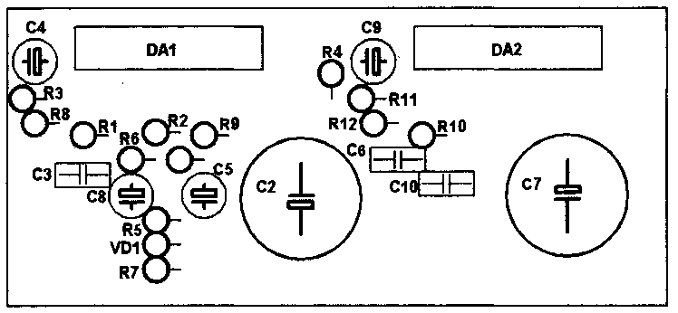
Below is a board layout with views from the elements and conductors, created using the Sprint-Layout_6.0 program.
Quite simple, even a person who is not very strong in electrical engineering can repeat it. The ULF on this chip will be ideal for use as part of an acoustic system for home computer, TV, cinema. Its advantage is that it does not require fine adjustment and tuning, as is the case with transistor amplifiers. And what can we say about the difference from lamp designs - the dimensions are much smaller.
Not required high voltage for powering anode circuits. Of course, there is heating, as in lamp designs. Therefore, if you plan to use the amplifier for a long time, it is best to install, in addition to an aluminum radiator, at least a small fan for forced airflow. Without it, the amplifier circuit on the TDA7294 microassembly will work, but there is a high probability of it going into temperature protection.
Why TDA7294?
This chip has been very popular for more than 20 years. It has won the trust of radio amateurs, since it has very high characteristics, the amplifiers based on it are simple, and anyone, even a novice radio amateur, can repeat the design. The amplifier on the TDA7294 chip (the circuit is shown in the article) can be either monophonic or stereophonic. The internal structure of the microcircuit consists of an Amplifier audio frequency, built on this chip, belongs to class AB.
Advantages of the microcircuit
Advantages of using a microcircuit for:
1. Very high power output. About 70 W if the load has a resistance of 4 ohms. In this case, the usual circuit for connecting the microcircuit is used.
2. About 120 W at 8 ohms (bridged).
3. Very low level of extraneous noise, distortion is insignificant, reproduced frequencies lie in the range that is completely perceivable by the human ear - from 20 Hz to 20 kHz.
4. The microcircuit can be powered from a source DC voltage 10-40 V. But there is a small drawback - you need to use a bipolar power source.
It is worth paying attention to one feature - the distortion coefficient does not exceed 1%. On the TDA7294 microassembly, the power amplifier circuit is so simple that it’s even surprising how it allows you to get such high-quality sound.
Purpose of the microcircuit pins

And now in more detail about what conclusions the TDA7294 has. The first leg is the “signal ground”, connected to the common wire of the entire structure. Pins “2” and “3” are inverting and non-inverting inputs, respectively. The "4" pin is also the "signal ground" connected to the common wire. The fifth leg is not used in audio amplifiers. “6” leg is a volt add-on; an electrolytic capacitor is connected to it. “7” and “8” pins are plus and minus power supply for the input stages, respectively. Leg “9” – standby mode, used in the control unit.
Similarly: “10” leg - muting mode, also used when designing an amplifier. “11” and “12” pins are not used in the design of audio amplifiers. The output signal is removed from the “14” pin and supplied to sound system. “13” and “15” pins of the microcircuit are “+” and “-” for connecting the power to the output stage. On the TDA7294 chip, the circuit is no different from those proposed in the article, it is supplemented only by the circuit that is connected to the input.
Features of microassembly

When designing an audio amplifier, you need to pay attention to one feature - the minus power supply, and these are the legs “15” and “8”, electrically connected to the microcircuit body. Therefore, it is necessary to isolate it from the radiator, which will be used in the amplifier in any case. For this purpose it is necessary to use a special thermal pad. If you are using a bridge amplifier circuit on the TDA7294, pay attention to the housing design. It can be vertical or horizontal type. The most common version is designated TDA7294V.
Protective functions of the TDA7294 chip

The microcircuit provides several types of protection, in particular, against supply voltage drop. If the supply voltage suddenly changes, the microcircuit will go into protection mode, therefore, there will be no electrical damage. The output stage also has overload protection and short circuit. If the device body heats up to a temperature of 145 degrees, the sound turns off. When 150 degrees is reached, it switches to standby mode. All pins of the TDA7294 chip are protected from electrostatics.
Amplifier
Simple, accessible to everyone, and most importantly - cheap. In just a few hours you can assemble a very good audio amplifier. Moreover, you will spend most of the time etching the board. The structure of the entire amplifier consists of power and control units, as well as 2 ULF channels. Try to use as few wires as possible in the amplifier design. Follow simple recommendations:
1. A prerequisite is to connect the power source with wires to each ultrasonic circuit board.
2. Tie the power wires into a bundle. With this you can slightly compensate for the magnetic field that is created electric shock. To do this, you need to take all three power wires - “common”, “minus” and “plus”, and with a little tension weave them into one braid.
3. Under no circumstances use so-called “earth loops” in the design. This is the case when the common wire connecting all the blocks of the structure is closed into a loop. The ground wire must be connected sequentially, starting from the input terminals further to the ultrasonic circuit board, and ending at the output connectors. It is extremely important to connect the input circuits using shielded and insulated wires.
Control unit for standby and muting modes

This chip also has muting. Functions must be controlled using pins “9” and “10”. The mode is turned on if there is no voltage on these legs of the microcircuit, or it is less than one and a half volts. To enable the mode, it is necessary to apply a voltage to the legs of the microcircuit, the value of which exceeds 3.5 V. In order for the amplifier boards to be controlled simultaneously, which is important for bridge-type circuits, one control unit is assembled for all stages.
When the amplifier is turned on, all the capacitors in the power supply are charged. There is also one capacitor in the control unit that stores charge. When the maximum possible charge is accumulated, the standby mode is turned off. The second capacitor used in the control unit is responsible for the operation of the muting mode. It charges a little later, so the mute mode turns off second.
Supplementing the TDA7294 microcircuit with powerful complementary transistors controlled from its output stage increases the rated output power of the UMZCH to 100 W with a 4 Ohm load. In addition to domestic transistors, more powerful imported ones can be recommended for this purpose. The author's use of a low-noise fan - a "cooler" from a computer processor - in the design made it possible to reduce the size of the heat sinks and amplifier.
The UMZCH based on the TDA7294 chip has gained well-deserved popularity among radio amateurs. At a minimum cost, you can assemble a high-quality UMZCH.
The amplifier version based on the TDA7294 chip turns out to be more reliable when operating with a real load, but its main specifications remain the same: the coefficient of nonlinear distortion, which is small for an output power of 5 W, increases to 0.5% at a power of more than 50 W. It is not possible to achieve an output power of more than 80 W with a 4 ohm load. The bridge circuit for connecting the microcircuit, recommended by the manufacturer, does not provide for the ability to work with a load with a resistance of 4 ohms.
The version of the amplifier shown here, its circuit shown in Fig. 1, solves the problem of increasing the output power and reducing the coefficient of nonlinear distortion with an output power of more than 50 W compared to a typical microcircuit circuit. To reduce the load on the output stage of the microcircuit, an additional push-pull repeater is built in at powerful bipolar transistors, which operate in mode B. There are no ladder-type distortions in the output stage because the output of the microcircuit is also connected to the load through a low-resistance resistor, and the OOS voltage is removed from the emitter circuit of additional transistors. Resistor R7 ensures rapid discharge of the capacitance of the emitter junctions of the output stage transistors.
Main technical characteristics:
Input impedance: 22 kOhm
Input voltage: 0.8V
Rated output power: 100W/4ohm
Reproducible frequency band: 20 – 20000 Hz
The disadvantage of the proposed UMZCH, in comparison with the version using a standard microcircuit connection circuit, is a steeper increase in nonlinear distortions at an output power close to the maximum. In a typical circuit, the output signal limitation has a “softer” character.
Simplified structural scheme TDA7294 shown in Fig. 1 allows us to make the following assumption. In the circuits of the output transistors of the microcircuit, resistive current sensors are included, therefore, when the output signal voltage is close to the supply voltage (when the current through powerful transistors microcircuit is maximum), the protection unit begins to smoothly limit the current in the load, field effect transistors output stage probably also contribute to softer clipping. The additional transistors of this UMZCH are not covered by such a tracking circuit, and a “hard” limitation of the output signal occurs, which is noticeable by ear.
A decrease in capacitance C6, C7 in comparison with that indicated in the diagram leads to unstable operation of the UMZCH at high power, but an increase in capacitance can lead to failure of transistors VT1, VT2, since when shorted in the load, the microcircuit protection unit does not always provide reliable protection for additional transistors until the fuses FU1, FU2 trip. The amplifier is powered by an unstabilized power supply from a 220 V network.
Not all parts purchased on radio markets are different high quality. There are microcircuits that are prone to self-excitation. In the described embodiment, self-excitation of some microcircuits must be eliminated by selecting capacitor C6.
In the UMZCH according to the scheme proposed here, even with slight self-excitation, “step” type distortions occur. If it is not possible to replace the “unsuccessful” microcircuit, the effect can be eliminated by soldering a capacitor with a capacity of 0.047-0.15 μF in parallel with resistor R7. Self-excitation is also eliminated by reducing the depth of feedback (increasing the resistance of resistor R3), while increasing the sensitivity of the amplifier.
Parts used in the amplifier:
- MLT resistors
- capacitors C1 - K73-17, KM-6; S2 – KT-1, KM-5; C8 – K73-17; SZ-S7 - K50-35 or imported.
- choke L1 - 25 turns of PEV-2 wire with a diameter of 1 mm - wound on a frame with a diameter of 5 mm in two layers.
Two amplifier channels are assembled on a printed circuit board made of one-sided foil fiberglass 2 mm thick; its drawing with the arrangement of elements is shown in Fig. 2 (the outline of the fans is conditionally transparent).

There is no space provided on the printed circuit board for blocking capacitors C9, C10. The use of transistors that differ significantly in the base current transfer coefficient has practically no effect on reliability and sound quality.
The absence of quiescent current allows you to use a fan (“cooler”) from a Pentium processor to cool the heat sinks of both channels of the amplifier. The board and fans must be installed so that the flow of warm air does not heat other parts of the amplifier.
Powerful transistors are mounted parallel to the plane of the printed circuit board with a metal surface of the heat sink to the cooler. On the flat side of the cooler, it is necessary to drill through holes with a diameter of 2.5 mm, coinciding with the holes in the printed circuit board, then cut the MZ thread. Through the holes in the board, the fan is pressed against the transistors with screws. Thin mica spacers must be placed on them and lubricated with heat-conducting paste.
Under the heads of the screws on the side of the tracks, you need to place washers with a diameter of 10-12 mm or a small metal plate in order to firmly press the transistors to the surface of the heat sink. Between printed circuit board and transistors, place thin cardboard 0.5-0.8 mm thick, it will ensure uniform pressing of the transistors to the plane of the fan, since their thickness is not always the same, even for those manufactured in the same production batch.
The DA1 chip is located on an additional heat sink with an effective surface area of at least 50 cm 2 .


It is advisable to “strengthen” the tracks on the printed circuit board through which the supply voltage is supplied to the output transistors by soldering tinned copper wire with a diameter of about 1 mm along them.
An amplifier assembled from serviceable parts does not require adjustment and can be repeated even by novice radio amateurs. Operation for two years showed its high reliability.
With new wiring, as well as with mounting the microcircuit and transistors on one radiator.
Now the editorial office website will show several versions of the famous low-budget audio power amplifier based on two TDA7294 chips. The amplifier is designed to connect two speakers with a power of 150 W each. The circuits and preamplifiers are assembled on the basis of circuitry common for this m/s, so we will not present them again - .
There is a preamplifier with regulators and a power amplifier. Symmetrical power supply +/- 40 V based on a 2x28V transformer and two 10000 µF capacitors. Two mono preamps, running in parallel with an 18V supply from the LM7818, drive the TDA chips. Everything is cooled inside the case by a fan, but due to the heating of the radiators, they were taken outside the case. The maximum power output is almost 2 x 100W (4 ohms) or 200W into the bridge. Everything fits into the computer power supply case. The amplifier operates stably and without any unpleasant extraneous sounds.
Parameters of the TDA7294 chip
- Continuous output power - 70 W (4 ohm load at +/- 27 V)
- Harmonic distortion - 0.005% (5 W, 1 kHz)
- Limit voltage - +/- 50 V (recommended 10 - 40 V)
This homemade UMZCH really has a relatively high output power and small size. The cost of implementing the project was within 1000 rubles. The case and transformer were received free of charge.
Photos of the ULF design on the TDA7294

True, with this transformer such power will be achievable only at signal peaks. Taking into account the proportions of the power supply and transformer, it has no more than 100W, which is not enough for long-term RMS. But also to become like Chinese manufacturers pocket tape recorders, drawing hundreds of watts of PMPO (maximum peak power output) on them, too. In reality, up to 70 W per channel can be extracted from the microcircuit, which in any case is not bad for a home.

Nowadays, most devices such as audio amplifiers use toroidal transformers (circular) because they take up less space, have more power and dissipate less magnetic field, but unfortunately they have one disadvantage. When turned on, a so-called current pulse occurs, which can reach a value several times greater than the power of the transformer. The result is that the fuses in electrical network. Moreover, the capacitors in the middle of the amplifier create an additional short circuit when the power is turned on, which can damage the power terminals and parts.

For all transformers (especially toroids) in the power supply, current delay protection () should be used, since at the moment the transformer is turned on there will be an inrush current several times higher than the rated current, for example: for 500 VA the rated current is about 2 A, and when turned on it can reach 12 A.


How does the security system work? The operation consists of temporarily limiting the current flowing during switching on of the transformer, so that inrush current does not occur. After approximately 2 seconds, the relay turns on and the transformer returns to normal operation. The entire circuit is built on a separate printed circuit board, its assembly is very simple.

With the TDA7294 it is difficult to achieve the desired 100 W. Therefore, a 120 W transformer is quite suitable. With it, a power of about 2 x 60W and no more can be achieved.
In general, having played enough with TDA and LM, we recommend looking away STK4241 or STK4050. They are truly more powerful and better sound amplifiers. As for LM or TDA, they cannot even be compared with STK in terms of distortion coefficient. So if you are going to make a really decent amplifier with a power of 2 x 100 W, do it with two STK4050 (according to the passport, they will safely issue 200 each). In the process of amateur radio practice, a total of 10 amplifiers were made on STK, and no one let us down.
Low-frequency power amplifier of the Hi-Fi class, made using a bridge circuit using two TDA7294 integrated circuits. Allows you to get up to 170 watts of output power, perfect for a subwoofer.
Specifications
- Output power at 8 Ohm load and power supply ±25V - 150 W;
- Output power at 16 Ohm load and ±35V power supply - 170 W.
Schematic diagram
The amplifier has output stage protection against short circuit, thermal protection (switching to reduced power in case of overheating that occurs under heavy loads), surge protection, shutdown mode (Standby), input signal on/off mode (Mute), and protection from a “click” when turning on/off. All this has already been implemented in TDA7294 integrated circuits.
Rice. 1. Bridge circuit for connecting two TDA7294 microcircuits - a powerful bridge low-frequency amplifier.
Parts and PCB

Rice. 2. Printed circuit board for the bridge version of the inclusion of TDA7294 microcircuits.
Rice. 3. Location of components for the bridge version of the inclusion of TDA7294 microcircuits.
To power such a power amplifier, you need a power source with a transformer with a power of at least 250-300 watts. In the rectifier circuit, it is advisable to install electrolytic capacitors of 10,000 μF or more on each arm.
Bridge circuit from the datasheet

Rice. 4. Bridge circuit for connecting two TDA7294 microcircuits (from the datasheet).
In bridge mode, the load resistance must be at least 8 ohms, otherwise the microcircuits will burn out from overcurrent!
Printed circuit board
Universal printed circuit board for two-channel and bridged power amplifier options.
The bridge circuit for switching on the UMZCH consists of two identical channels, in one of which the signal input is connected to ground, and the feedback input (leg 2) is connected through a 22K resistor to the output of the second channel.
Also, the 10th legs of the microcircuits (Mute) and the 9th legs (Stand-By) need to be connected to a mode control circuit assembled using resistors and capacitors (Figure 6).

Rice. 5. Printed circuit board for a power amplifier based on TDA7294 chips.
The boards have slight deviations (for the better) from the diagram from the datasheet:
- At the inputs of the microcircuits (pin 3), 4 µF capacitors are installed, not 0.56 µF;
- A 470 µF capacitor is connected between the 680 Ohm resistor (which goes to pin 2) and ground;
- The capacitors between legs 6 and 14 are 470 µF, not 22 µF;
- For power supply, instead of 0.22 µF capacitors, it is proposed to install 680 nF (0.68 µF);
In a bridge connection, pins 10 and 9 are connected together respectively and connected to the mode control circuit.

Rice. 6. Simple scheme control of Standby-Mute modes for TDA7294 chips.
To turn on the microcircuits (take them out of quiet and energy-saving modes), the “VM” and “VSTBY” contacts just need to be connected to the positive +Vs power supply pin.
This printed circuit board is universal; it can be used for both dual-channel and bridge modes of operation of the amplifier on TDA7294 chips. The ground wiring (GND) is very well done here, which will improve the reliability and noise immunity of the UMZCH.
Literature:
- Datasheet for the TDA7294 chip - Download (7-Zip archive, 1.2MB).
- FAQ for TDA7294 - cxem.net/sound/amps/amp129.php
