DIY air temperature sensor. DIY thermostat: simple instructions and connection diagram. Operating principle and setup at home. How it works
A simple DIY electronic thermostat. I propose a method for making a homemade thermostat to maintain a comfortable room temperature in cold weather. The thermostat allows you to switch power up to 3.6 kW. The most important part of any amateur radio design is the housing. A beautiful and reliable case will ensure a long life for any homemade device. The version of the thermostat shown below uses a convenient, small-sized case and all the power electronics from an electronic timer sold in stores. Homemade electronic part built on the LM311 comparator chip.
Description of the circuit operation
The temperature sensor is a thermistor R1 with a nominal value of 150k, type MMT-1. Sensor R1 together with resistors R2, R3, R4 and R5 form a measuring bridge. Capacitors C1-C3 are installed to suppress interference. Variable resistor R3 balances the bridge, that is, it sets the temperature.
If the temperature of temperature sensor R1 drops below the set value, its resistance will increase. The voltage at input 2 of the LM311 microcircuit will become greater than at input 3. The comparator will work and its output 4 will set to a high level, the voltage applied to the electronic timer circuit through the HL1 LED will cause the relay to operate and turn on the heating device. At the same time, the HL1 LED will light up, indicating that the heating is turned on. Resistance R6 creates negative feedback between output 7 and input 2. This allows you to set hysteresis, that is, the heating turns on at a temperature lower than it turns off. Power is supplied to the board from the electronic timer circuit. Resistor R1 placed outside requires careful insulation, since the thermostat’s power supply is transformerless and has no galvanic isolation from the network, that is dangerous mains voltage present on device elements. The manufacturing procedure for the thermostat and how the thermistor is insulated is shown below.
How to make a thermostat with your own hands
1. The donor of the housing and power circuit is opened - the CDT-1G electronic timer. A timer microcontroller is installed on a gray three-wire cable. Unsolder the cable from the board. The holes for the cable wires are marked (+) - +5 Volt power supply, (O) - control signal supply, (-) - minus power supply. An electromagnetic relay will switch the load.
2. Since the power supply to the circuit from the power unit is not galvanically isolated from the network, all work on checking and setting up the circuit is carried out from a safe 5 volt power source. First, we check the functionality of the circuit elements at the stand.
3. After checking the circuit elements, the design is assembled on the board. The board for the device was not developed and was assembled on a piece of a breadboard. After assembly, a performance check is also carried out on the stand.
4. Thermal sensor R1 is installed externally on the side surface of the socket housing; the conductors are insulated with heat-shrinkable tubing. To prevent contact with the sensor, but also to maintain access of outside air to the sensor, a protective tube is installed on top. The tube is made from the middle part of a ballpoint pen. A hole is cut in the tube for installation on the sensor. The tube is glued to the body.
5. Variable resistor R3 is installed on the top cover of the case, and a hole for the LED is also made there. It is useful to cover the resistor body with a layer of electrical tape for safety.
6. The adjustment knob for resistor R3 is homemade and made with your own hands from an old toothbrush of a suitable shape :).
Resistor R3A thermostat on the farm is sometimes an irreplaceable thing that helps control the thermal conditions in a home incubator or vegetable drying. Built-in mechanisms for this purpose often quickly deteriorate or are not of decent quality, which forces you to invent a simple thermostat yourself.
If you are among those who urgently need a homemade device with a heat regulation function, stay here, because all suitable and tested schemes are combined with theory and useful tips are given below.

What is it applicable for?
A temperature controller or thermostat is a device that can start and stop the operation of heating or cooling units. For example, it allows you to maintain optimal conditions in the incubator, and is also able to turn on heating in the basement, fixing a low temperature.

How it works?
Before you make a thermostat with your own hands, you need to understand the accompanying theory. Principle of this device is identical to the operation of simple measurement sensors capable of changing resistance depending on surrounding temperature conditions. A special element is responsible for changing the indicator, and the so-called reference resistance remains unchanged.

In the thermostat device, an integrated amplifier (comparator) reacts to changes in the resistance value, switching the microcircuits when a certain temperature is reached.


What should the scheme be?
On the Internet and in regulatory documentation, it is easy to find diagrams of thermostats for various purposes that you can assemble with your own hands. In most cases, the basis of a schematic drawing is the following elements:
- Control zener diode, designated TL431;
- Integrated amplifier (K140UD7);
- Resistors (R4, R5, R6);
- Quenching capacitor (C1);
- Transistor (KT814);
- Diode bridge (D1).

The circuit is powered by a transformerless power supply, and a car relay designed for a voltage of 12 Volts is ideal as an actuator, provided that the current supplied to the coil is at least 100 mA.

How to do it?
Instructions for making a thermostat with your own hands are based on strict adherence to the chosen scheme, according to which it is necessary to connect all the components into a single whole. For example, electronic circuit for the incubator is assembled according to the following algorithm:
- Study the image (it’s better to print it out and put it in front of you).
- Find the necessary parts, including the case and board (old ones from the meter will do).
- Start with the “heart” - the K140UD7/8 integrated amplifier, connecting it with a positively charged reverse action, which will give it the functions of a comparator.
- Connect the negative resistor MMT-4 in place of “R5”.
- Connect the remote sensor using shielded wiring, and the cord length can be no more than a meter.
- To control the load, include thyristor VS1 in the circuit, installing it on a small radiator to ensure adequate heat transfer.
- Set up the remaining elements of the circuit.
- Connect to the power supply.
- Check functionality.

By the way, by adding a temperature sensor, the assembled device can be safely used not only for incubators, drying, but also for maintaining the thermal regime in an aquarium or terrarium.


How to install correctly?
In addition to high-quality assembly, it is necessary to pay attention to the operating conditions, which should include:
- Location – Bottom part rooms;
- Dry room;
- The absence of nearby “knocking” units: emitting heat or cold (electrical equipment, air conditioning, open door with a draft).

Having figured out how to connect the thermostat with your own hands, you can start installing it regular use. The main thing is that the power of the manufactured device is designed for the relay contacts. For example, when maximum load at 30 Amps, the power should not exceed 6.6 kW.

How to repair?
A factory or homemade thermostat can be repaired so as not to buy a new one and not waste time searching and assembling the necessary parts. First of all, you need to find the device (if you were not the one who installed it), because from the photo of the thermostat you can see that its dimensions are small, which makes the search somewhat difficult.

A tip will help: the thermostat is located next to the temperature mode button.
Signs of device failure may include the following:
- The device has ceased to perform its main function: the temperature has dropped or increased significantly without the mechanism reacting;
- The connected device works without going into standby or saving mode;
- The unit turned off spontaneously.
Depending on the cause of the malfunction, you must take the following steps to repair the thermostat yourself:
- Disconnect the device being repaired from the network.
- Remove the protective housing from the device.
- Check the quality of contacts and connections.
- Disconnect and pull out the capillary tube.
- Get the relay.
- Change the bellows tube and secure it.
- If necessary, replace other parts.
- Reconnect the wiring.
- Put the relay in place.


Many household and household appliances are equipped with thermostats, and knowing how to repair them, reassemble them with your own hands and install them will significantly save your money, time and effort.


DIY thermostat photo


The need to adjust the temperature regime arises when using various systems heating or refrigeration equipment. There are many options, and they all require a control device, without which the systems can operate either in maximum power mode or at a complete minimum of capabilities. Control and adjustment are carried out using a thermostat - a device that can influence the system through a temperature sensor and turn it on or off as needed. When using ready-made equipment kits, control units are included in the delivery package, but for homemade systems you have to assemble the thermostat yourself. The task is not the easiest, but quite solvable. Let's take a closer look at it.
The principle of operation of the thermostat
A thermostat is a device that can respond to changes in temperature. Based on the type of action, a distinction is made between trigger-type thermostats, which turn off or turn on heating when a specified limit is reached, or smooth-action devices with the ability to fine-tune and accurately adjust, capable of controlling temperature changes in the range of fractions of a degree.
There are two types of thermostats:
- Mechanical. It is a device that uses the principle of expansion of gases when temperature changes, or bimetallic plates that change their shape when heated or cooled.
- Electronic. It consists of a main unit and a temperature sensor that sends signals about an increase or decrease in the set temperature in the system. Used in systems requiring high sensitivity and fine adjustment.
Mechanical devices do not allow for high precision settings. They are both a temperature sensor and an actuator, combined into a single unit. A bimetallic strip used in heating devices is a thermocouple made of two metals with different coefficients of thermal expansion.
The main purpose of the thermostat is to automatically maintain the required temperature
When heated, one of them becomes larger than the other, causing the plate to bend. The contacts installed on it open and stop heating. When cooled, the plate returns to its original shape, the contacts close again and heating resumes.
The chamber with the gas mixture is a sensitive element of the refrigerator thermostat or heating thermostat. When temperature changes, the volume of gas changes, which causes movement of the surface of the membrane connected to the lever of the contact group.
The thermostat for heating uses a chamber with a gas mixture that works according to Gay-Lussac's law - when the temperature changes, the volume of gas changes
Mechanical thermostats are reliable and provide stable operation, but the operating mode is adjusted with a large error, almost “by eye”. If necessary fine tuning, providing adjustment within a few degrees (or even finer), electronic circuits are used. The temperature sensor for them is a thermistor, which is capable of distinguishing the smallest changes in the heating mode in the system. For electronic circuits, the situation is the opposite - the sensitivity of the sensor is too high and it is artificially coarsened, bringing it to the limits of reason. The principle of operation is a change in the resistance of the sensor caused by fluctuations in the temperature of the controlled environment. The circuit reacts to changes in signal parameters and increases/decreases heating in the system until another signal is received. The capabilities of electronic control units are much higher and allow you to obtain temperature settings of any accuracy. The sensitivity of such thermostats is even excessive, since heating and cooling are processes with high inertia, which slow down the reaction time to changing commands.
Scope of homemade device
Making a mechanical thermostat at home is quite difficult and irrational, since the result will operate in too wide a range and will not be able to provide the required adjustment accuracy. Most often, homemade electronic thermostats are assembled, which allow you to maintain the optimal temperature of a heated floor, incubator, provide the desired water temperature in the pool, heat the steam room in the sauna, etc. There can be as many options for using a homemade thermostat as there are systems in the house that need to be configured and adjusted. For rough adjustments using mechanical devices It’s easier to purchase ready-made elements; they are inexpensive and quite accessible.
Advantages and disadvantages
A homemade thermostat has certain advantages and disadvantages. The advantages of the device are:
- High maintainability. A thermostat made by yourself is easy to repair, since its design and operating principle are known to the smallest detail.
- The costs of creating a regulator are much lower than when purchasing a ready-made unit.
- It is possible to change the operating parameters to obtain a more suitable result.
The disadvantages include:
- The assembly of such a device is accessible only to people who have sufficient training and certain skills in working with electronic circuits and a soldering iron.
- The quality of operation of the device largely depends on the condition of the parts used.
- The assembled circuit requires adjustment and alignment on a control stand or using a reference sample. It is impossible to obtain a ready-made version of the device immediately.
The main problem is the need for training or, at a minimum, the participation of a specialist in the process of creating the device.
How to make a simple thermostat
The manufacture of a thermostat occurs in stages:
- Selecting the type and circuit of the device.
- Acquisition necessary materials, tools and parts.
- Device assembly, configuration, commissioning.
The manufacturing stages of the device have their own characteristics, so they should be considered in more detail.
Necessary materials
Materials required for assembly include:
- Foil getinax or circuit board;
- Soldering iron with solder and rosin, ideally a soldering station;
- Tweezers;
- Pliers;
- Magnifier;
- Wire cutters;
- Insulating tape;
- Copper connecting wire;
- Necessary parts according to the electrical diagram.
During the work process, you may need other tools or materials, so this list should not be considered exhaustive or definitive.
Device diagrams
The choice of scheme is determined by the capabilities and level of training of the master. How more complicated scheme, the more nuances will arise when assembling and configuring the device. At the same time the most simple circuits make it possible to obtain only the most primitive instruments operating with a high error.
Let's consider one of the simple schemes.
In this circuit, a zener diode is used as a comparator
The figure on the left shows the regulator circuit, and on the right is the relay block that turns on the load. The temperature sensor is resistor R4, and R1 is a variable resistor used to adjust the heating mode. The control element is a zener diode TL431, which is open as long as there is a load on its control electrode above 2.5 V. Heating of the thermistor causes a decrease in resistance, causing the voltage on the control electrode to drop, the zener diode closes, cutting off the load.
The other scheme is somewhat more complicated. It uses a comparator - an element that compares the readings of a temperature sensor and a reference voltage source.
A similar circuit with a comparator is applicable for adjusting the temperature of a heated floor.
Any change in voltage caused by an increase or decrease in the resistance of the thermistor creates a difference between the standard and the operating line of the circuit, as a result of which a signal is generated at the output of the device, causing the heating to turn on or off. Such schemes, in particular, are used to regulate the operating mode of heated floors.
Step-by-step instruction
The assembly procedure for each device has its own characteristics, but some general steps can be identified. Let's look at the build progress:
- We prepare the device body. This is important because the board cannot be left unprotected.
- We are preparing the payment. If you use foil getinax, you will have to etch the tracks using electrolytic methods, having first painted them with paint insoluble in the electrolyte. A circuit board with ready-made contacts greatly simplifies and speeds up the assembly process.
- Using a multimeter, we check the performance of the parts and, if necessary, replace them with serviceable samples.
- According to the diagram, we assemble and connect all the necessary parts. It is necessary to ensure the accuracy of the connection, correct polarity and direction of installation of diodes or microcircuits. Any mistake can lead to the failure of important parts that will have to be purchased again.
- After completing assembly, it is recommended to carefully inspect the board again, check the accuracy of the connections, the quality of soldering and other important points.
- The board is placed in the case, a test run is carried out and the device is configured.
How to setup
To configure the device, you must either have a reference device or know the voltage rating corresponding to a particular temperature of the controlled environment. For individual devices there are own formulas, showing the dependence of the voltage on the comparator on temperature. For example, for the LM335 sensor this formula looks like:
V = (273 + T) 0.01,
where T is the required temperature in Celsius.
In other schemes, adjustment is made by selecting the values of adjusting resistors when creating a certain, known temperature. In each specific case, our own methods can be used, optimally suited to the existing conditions or equipment used. The requirements for the accuracy of the device also differ from each other, so in principle there is no single adjustment technology.
Basic faults
The most common malfunction of homemade thermostats is instability of the thermistor readings caused by poor quality parts. In addition, there are often difficulties with setting modes caused by mismatches in ratings or changes in the composition of parts required for proper operation devices. Majority possible problems directly depend on the level of training of the technician who assembles and configures the device, since skills and experience in this matter mean a lot. However, experts say that making a thermostat with your own hands is a useful practical task that gives good experience in creating electronic devices.
If you don’t have confidence in your abilities, it’s better to use a ready-made device, of which there are plenty on sale. It must be taken into account that a regulator failure at the most inopportune moment can cause serious troubles, the elimination of which will require effort, time and money. Therefore, when deciding on self-assembly, you should approach the issue as responsibly as possible and carefully weigh your options.
The reason for assembling this circuit was the breakdown of the thermostat in the electric oven in the kitchen. Having searched on the Internet, I didn’t find a particular abundance of options on microcontrollers, of course there are some, but all are mainly designed to work with a temperature sensor like DS18B20, and it is very limited in the temperature range of upper values and is not suitable for the oven. The task was to measure temperatures up to 300°C, so the choice fell on K-type thermocouples. Analysis of circuit solutions led to a couple of options.
Thermostat circuit - first option
The thermostat assembled according to this scheme has a declared upper limit of 999°C. This is what happened after assembling it:

Tests have shown that the thermostat itself works quite reliably, but I didn’t like the lack of flexible memory in this version. Sewing the microcontroller for both options is in the archive.

Thermostat circuit - second option

After some thought, I came to the conclusion that it is possible to connect here the same controller as on the soldering station, but with a little modification. During the operation of the soldering station, minor inconveniences were identified: the need to set the timers to 0, and sometimes an interference occurs that switches the station to the SLEEP . Considering that women do not need to remember the algorithm for switching the timer to mode 0 or 1, the circuit of the same station was repeated, but only the hair dryer channel. And minor improvements led to stable and “interference-free” operation of the thermostat in terms of control. When flashing AtMega8 firmware, you should pay attention to the new fuses. The following photo shows a K-type thermocouple, which is convenient to mount in the oven.

I liked the work of the temperature controller on the breadboard - I started the final assembly on printed circuit board.

I finished the assembly, the operation is also stable, the readings in comparison with the laboratory thermometer differ by about 1.5°C, which is basically excellent. When setting up, there is an output resistor on the printed circuit board; I have not yet found an SMD of this value in stock.

The LED models the heating elements of the oven. The only note: the need to create a reliable common ground, which in turn affects the final measurement result. The circuit requires a multi-turn tuning resistor, and secondly, pay attention to R16, it may also need to be selected, in my case it is 18 kOhm. So, here's what we have:

In the process of experimenting with the latest thermostat, more minor improvements appeared that qualitatively affected the final result, look at the photo with the inscription 543 - this means the sensor is disconnected or broken.

And finally we move from experiments to the finished design of the thermostat. I implemented the circuit into the electric stove and invited an authoritative commission to accept the work :) The only thing that my wife rejected were the small buttons on the convection control, general power supply and airflow, but this can be solved over time, but for now it looks like this.

The regulator maintains the set temperature with an accuracy of 2 degrees. This happens at the moment of heating, due to the inertia of the entire structure (the heating elements cool down, the internal frame is temperature equalized), in general, I really liked the scheme in the work, and therefore it is recommended for independent repetition. Author - GOVERNOR.
Discuss the article THERMOREGULATOR DIAGRAM
In this article we will consider devices that support a certain thermal regime, or signal when the desired temperature value has been reached. Such devices have a very wide scope of application: they can maintain a given temperature in incubators and aquariums, heated floors, and even be part of smart home. For you, we have provided instructions on how to make a thermostat with your own hands and at a minimum cost.
A little theory
The simplest measuring sensors, including those that respond to temperature, consist of a measuring half-arm of two resistances, a reference and an element that changes its resistance depending on the temperature adjusted to it. This is shown more clearly in the picture below.
As can be seen from the diagram, resistor R2 is the measuring element of a homemade thermostat, and R1, R3 and R4 are the reference arm of the device. This is a thermistor. It is a conductor device that changes its resistance with temperature changes.

The thermostat element that responds to changes in the state of the measuring arm is an integrated amplifier in comparator mode. This mode abruptly switches the output of the microcircuit from the off state to the operating position. Thus, at the output of the comparator we have only two values “on” and “off”. The load of the chip is a PC fan. When the temperature reaches a certain value in the arm R1 and R2, a voltage shift occurs, the input of the microcircuit compares the value on pins 2 and 3 and the comparator switches. The fan cools the required object, its temperature drops, the resistance of the resistor changes and the comparator turns off the fan. In this way, the temperature is maintained at a given level and the operation of the fan is controlled.
Overview of circuits
The difference voltage from the measuring arm is supplied to a paired transistor with a high gain, and an electromagnetic relay acts as a comparator. When the coil reaches a voltage sufficient to retract the core, it is triggered and connected through its contacts of actuators. When the set temperature is reached, the signal on the transistors decreases, the voltage on the relay coil synchronously drops, and at some point the contacts are disconnected and the payload is turned off.

A feature of this type of relay is the presence - this is a difference of several degrees between turning on and off a homemade thermostat, due to the presence of an electromechanical relay in the circuit. Thus, the temperature will always fluctuate a few degrees around the desired value. The assembly option provided below is practically free of hysteresis.
Schematic electronic circuit of an analog thermostat for an incubator:

This scheme was very popular for repetition in 2000, but even now it has not lost its relevance and copes with the function assigned to it. If you have access to old parts, you can assemble a thermostat with your own hands almost free of charge.
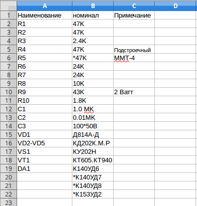
The heart of the homemade product is the K140UD7 or K140UD8 integrated amplifier. In this case it is connected with positive feedback and is a comparator. The temperature-sensitive element R5 is a resistor of type MMT-4 with negative TKE, which means that when heated its resistance decreases.
The remote sensor is connected via a shielded wire. To reduce and false trigger the device, the length of the wire should not exceed 1 meter. The load is controlled through thyristor VS1 and the maximum permissible power of the connected heater depends on its rating. In this case, a 150 Watt electronic switch - a thyristor - must be installed on a small radiator to remove heat. The table below shows the ratings of radio elements for assembling a thermostat at home.
The device does not have galvanic isolation from the 220 Volt network; when setting up, be careful; there is mains voltage on the regulator elements, which is life-threatening. After assembly, be sure to insulate all contacts and place the device in a non-conductive housing. The video below shows how to assemble a thermostat using transistors:
Homemade thermostat using transistors
Now we’ll tell you how to make a temperature controller for a heated floor. The working diagram is copied from a serial sample. It will be useful for those who want to familiarize themselves and repeat, or as a sample for troubleshooting the device.
The center of the circuit is a stabilizer chip connected in an unusual way, LM431 begins to pass current when the voltage is above 2.5 Volts. This is exactly the size of the internal reference voltage source for this microcircuit. At a lower current value, it does not pass anything. This feature began to be used in all kinds of thermostat circuits.
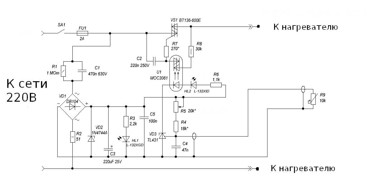
As you can see, the classic circuit with a measuring arm remains: R5, R4 are additional resistors, and R9 is a thermistor. When the temperature changes, the voltage shifts at input 1 of the microcircuit, and if it reaches the operating threshold, the voltage moves further along the circuit. In this design, the load for the TL431 microcircuit is the operation indication LED HL2 and optocoupler U1, for optical isolation of the power circuit from the control circuits.
As in the previous version, the device does not have a transformer, but receives power from the quenching capacitor circuit C1, R1 and R2, so it is also under life-threatening voltage, and you need to be extremely careful when working with the circuit. To stabilize the voltage and smooth out the ripples of network surges, a zener diode VD2 and a capacitor C3 are installed in the circuit. To visually indicate the presence of voltage, an HL1 LED is installed on the device. The power control element is a VT136 triac with a small harness for control via optocoupler U1.
At these ratings, the control range is within 30-50°C. Despite the apparent complexity at first glance, the design is simple to set up and easy to repeat. Visual diagram of a thermostat on a TL431 chip, with external power supply 12 volts for use in home automation systems are presented below:
This thermostat is capable of controlling a computer fan, power relays, indicator lights, and sound alarms. To control the temperature of the soldering iron, there is an interesting circuit using the same TL431 integrated circuit.

To measure the temperature of the heating element, a bimetallic thermocouple is used, which can be borrowed from a remote meter in a multimeter or purchased at a specialized radio parts store. To increase the voltage from the thermocouple to the trigger level of TL431, an additional amplifier is installed on LM351. Control is carried out through an optocoupler MOC3021 and triac T1.
When connecting the thermostat to the network, it is necessary to observe the polarity, the minus of the regulator must be on the neutral wire, otherwise phase voltage will appear on the body of the soldering iron, through the thermocouple wires. This is the main drawback of this scheme, because not everyone wants to constantly check that the plug is correctly connected to the socket, and if you neglect this, you can get an electric shock or damage electronic components during soldering. The range is adjusted by resistor R3. This scheme will ensure long-term operation of the soldering iron, eliminate its overheating and increase the quality of soldering due to the stability of the temperature regime.
Another idea for assembling a simple thermostat is discussed in the video:
Temperature controller on TL431 chip
A simple regulator for a soldering iron
The disassembled examples of temperature controllers are quite enough to satisfy the needs of a home craftsman. The schemes do not contain scarce and expensive spare parts, are easily repeated and practically do not require adjustment. These homemade products can easily be adapted to regulate the temperature of water in a water heater tank, monitor the heat in an incubator or greenhouse, and upgrade an iron or soldering iron. In addition, you can restore an old refrigerator by remaking the regulator to work with negative temperature values, by replacing the resistances in the measuring arm. We hope our article was interesting, you found it useful and understood how to make a thermostat with your own hands at home! If you still have questions, feel free to ask them in the comments.
