DIY oscilloscope from a smartphone. DIY oscilloscope from a tablet. Pros and cons of the above scheme
Long introduction.
I have never been a passionate smartphone fan. Probably the main reason for indifference to these devices is their size and lack of ability to work in a 3G network (my company has its own corporate communications with very favorable tariffs for conversations, but not for the Internet). In addition, due to the nature of my work, I need to have my phone with me all the time and in rather dirty conditions, with a high probability of dropping it or knocking it somewhere. It’s inconvenient for me to put my phone in different plastic bags, silicones, and cases, since I’m used to carrying my phone in my pockets. For this reason my old Sony Ericsson The K750 has been with me for several years now and there was no reason to replace it.
But then they send me on a business trip, and after it, I immediately go to a sanatorium to relax. In both places there were rather dubious options for accessing a computer, but free WiFi was promised in both hotels. Since I can’t abandon my Internet resources for such a long time, and I didn’t want to carry a laptop around with me at all, I decided to take a Google phone with me. And therefore, from my wife, amid dissatisfied exclamations :), the Galaxy Gio was taken away, and in return I was given my old Sony Ericsson.
To be honest, I liked Galaxy Gio even earlier because of its adequate dimensions and low price. And it was me who initiated the replacement of my wife’s old, dead folding phone with a Galaxy Gio.
Before the business trip, my acquaintance with Galaxy Gio was rather superficial - set up WiFi, account, some other little things... after the sanatorium, based on some experience with the phone, I came to the following conclusions:
— the phone’s dimensions are convenient (due to the fact that it is thinner than my Sonyerikson) and even gets in the way less in your pocket;
- synchronizing contacts with a Google account is a good thing (I was tired of transferring contacts via Bluetooth from the old phone to the new one), the loss of the phone will no longer be so catastrophic, since the contacts (the most valuable thing in the phone) are stored in the Google account;
— working on the network (in Opera), in principle, is tolerable, but the functionality is rather limited, which creates problems, for example, if you need to do something more than answer an email or post in a forum;
- enter text on touchpad undeniably more convenient than regular phone, but nothing can replace a regular keyboard and mouse;
- The gluttony of the phone is very annoying! Daily exercise is required. And since I had to schlep around on trains and make long journeys, I developed a strong instinct to save the battery (it’s good that there is a separate player, otherwise I can’t play games or listen to music on the road, because at the end of the journey you can easily be left without communication) . You also constantly carry a charger with you and look for an outlet at every station to plug into (before the smartphone, I perceived McDonald’s only as a place where you could have a snack in an unfamiliar city - now they have another function :)).
In general, in the end, despite certain shortcomings, I decided to keep the Galaxy Gio for permanent use (my wife bought herself the same one, only in white :))
Closer to the point.
Why such a long introduction? But to no avail! It was me who finally got to my computer and started scribbling text :). And in this article I wanted to talk about applications for Android that could be useful in the development of electronic devices.
It must be said right away that, due to the specifics of the Google Phone (it is, after all, a phone), you can’t count on anything serious, but what is there, we’re happy about it.
After wandering around on Google Play Store I have made a small selection, which, in my opinion, may be useful to you. The selection does not pretend to be complete, and if you know any interesting applications, write to me and I’ll add them.
1 LET'S START FROM THE MUST-HAVE APPLICATION.


The Market description reads: “ElectroDroid is a powerful toolkit and reference for the electronics developer.” One can argue about the “powerful set of tools”, but the fact that the application is the best in its field is for sure. ElectroDroid is easy to use, it has been translated into Russian (most of it), it contains a lot of reference information in various areas, there are calculations for basic circuits (LM317, NE555, op-amp...), convenient calculators for color marking of resistors, capacitors, chokes, pinouts of a large number of connectors and much more interesting things. Background information convenient to use, since pictures and text are automatically reformatted when rotated and scaled for easier reading.
To give you some idea of the form in which reference material is presented, here is an information strip on the USB connector:
The Market has both paid and free versions of the application. Much respect to the author for the fact that the free version is almost completely functional (except for the absence of individual sections and the presence of advertising).
2 GROUP OF ELECTRICAL CIRCUIT SIMULATORS.


Droid Tesla electrical circuit simulator, as described in the Market, based on the SPICE engine (what is that supposed to mean?). Also, the description boasts that the simulator uses Kirchhoff's laws (KCL) for resistive circuits (I would like to see a simulator that does not use these laws! They would also include the use of Ohm's law as an advantage :)). For nonlinear circuits Newton-Raphson algorithm is used... etc. and so on. In general, the description is generously strewn with mathematical terms - in short, it should work just fine (according to the description in the Market). I cannot say how plausibly the circuits are calculated, but from the examples it is clear that the circuits are quite complex. The application has many settings, the ability to create online projects, change color schemes. The main drawback is that the free version is absolutely unusable, since most of the components are missing (you can’t even really look at the examples).


Another simulator is EveryCircuit. Like the previous one, it boasts of various methods for calculating various circuits, but the main difference and advantage of this simulator is its visualization. In the literal sense of the word, you can see how current flows through the wires, LEDs light up with different brightness (even if the current allowed for them is exceeded, the effect of their burnout is drawn), graphs are drawn, etc. As you work, you can change the parameters of the elements using the interactive controller.
The application just asks to be put on the teacher’s tablet! With such an application, you can easily and clearly show lazy pupils/students how various components work in electrical circuit. Another advantage is that the authors free version We took the path of limiting the field for the circuit, rather than the number of components.
3 GROUP OF OSCILLOSCOPES AND SPECTRUM ANALYZERS.
Due to the fact that without the use of any hardware, an Android device can only receive a signal through a microphone (or headset), then frequency range lies in the region of 20 - 22,000 Hz (and this is in the best case). This greatly limits the scope of use of such oscilloscope-analyzers, turning them into toys, but, you never know, they might come in handy...


Nice oscilloscope. There are cursors, a trigger, an offset. Microphone input. The project is open, and if you can add something you need, you can get the source at android.serverbox.ch


An ascetic, without any settings, and according to the creators, a fast (High performance native code using OpenGL ES 2.0) spectrum analyzer. The declared range is 20 – 22,000 Hz, but we understand that it will be significantly narrower. The scale is logarithmic. Based on my testing, it's pretty accurate.
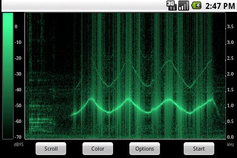

Another spectrum analyzer, but compared to the previous one, it does not just display the spectrum, but draws it in time. It turns out quite clearly. In the free version, the frequency range is limited to 8 kHz and the scale is linear. The paid version removes frequency restrictions, adds color schemes, and allows you to choose the scale type
4 GROUP OF GENERATORS.
Close in meaning to the previous group, but, it seems to me, more in demand. Again we can only count on an output range of 20 – 22,000 Hz. The signal can be sent to a speaker or through the audio jack (and amplifier, if necessary). There is only one application in this group so far, but it is very functional.


Quite a functional free generator. It can produce sine, square, saw, “white” and “pink” noise. For meander and saw, the duty cycle can be changed. In addition, it can create a signal with amplitude, frequency and phase modulation (and the modulating signal can also be a sine wave, square wave or sawtooth). The program can also automatically increase/decrease the frequency over time linearly or logarithmically. Everything is convenient, simple, and most importantly, there is no sticky attenuator handle, which developers love to stick into such programs.
5 GROUP FOR AVR DEVELOPER.


A reference guide to assembler commands for AVR. It’s not very convenient to use - there is no search and breakdown into groups - everything is in one list. Also, on my Gio, the text appears very faint. But let's not be harsh on the developer - he tried for us for free.
One of the rare useful things in the Market! A complete fuse calculator for AVR. Similar to http://www.engbedded.com/fusecalc. You check the boxes and you get fusebytes. Supports 144 crystals. Forms command line for AVRDUDE. Frequently used controllers can be marked as favorites - easier to find. For free. Required for installation.
Very interesting application. It can output a UART signal through the audio output. (If I still took it, it would be great). You can set the Baudrate and the delay between characters - there are no other settings. Since I always try to attach UART control to my devices, this application can turn the phone into a kind of control panel. To generate the required signal level, you need a converter cable. The developer offers the following scheme:

6 GROUP OF DATALOGERS.
There is often a need to record any parameters that extend over a long period of time; Android devices can be useful for this, since they are quite compact and have a whole arsenal of sensors on board. For example, you can attach a phone to an object and, by recording readings from position sensors, obtain the trajectory of the object's movement. You can also turn your phone into a video recorder or audio recorder. The scope of application is wide and such a number of different sensors is difficult to find anywhere else in one place.
A simple free program can record video (break it into parts if necessary) or take pictures with a given period. While recording, you can view sensor readings. Files are saved on the SD card in a directory SmartphoneLoggerData
Another free application. Works with a bunch of sensors: sound (microphone), acceleration, orientation, magnetic field, light, etc. In addition, and with exotic ones: battery charge, WIFI, Bluetooth, GPS, signal level, broadcast cell... The program saves data in CSV format, which allows you to subsequently “feed” it to any program, analyze it, draw a graph or make calculations. Files are saved on the SD card in a directory sensortrack divided into folders with the names of the sensors.
This is the entire list for now. I look forward to interesting additions from you.
(Visited 26,809 times, 8 visits today)
Developed her first virtual instrument, she created a new market and helped many developers evaluate the possibilities of using personal computer as a test and measurement platform. The availability of a PC for every developer became a driving force in the market at that time, making it possible to turn a PC or laptop into the basis of an instrumentation platform with inexpensive hardware and software data collection. Now, in addition to National Instruments, which has succeeded in this area, many other small companies have appeared on the market offering USB devices data collection, which are called USB/PC oscilloscopes.
But today, most electronics developers have smartphones, and it would be common for them to use their smartphone, if not as a test platform, then at least to display the data obtained. This opens up a new direction in the development of virtual devices.
The data acquisition hardware, combined with a computing platform, can be made very compact, smaller than a credit card.
This concept has given rise to two interesting virtual instruments available on the market today. We are talking about SmartScope from LabNation and Red Pitaya. Both projects are open source ( open source), and are developed based on Xilinx FPGAs. The signal frequency and amplitude displayed on the mobile phone can be changed using a conventional touch interface, eliminating the need for rotary knobs.
LabNation SmartScope
SmartScope costs about $200. Depending on the additional external peripherals included in the kit, the price may vary slightly, either down or up.
SmartScope can receive power via a connected smartphone USB cable or through external source USB power supply. SmartScope can perform the functions of not only an oscilloscope, but also a logic analyzer and signal generator.
SmartScope supports a variety of operating systems, including Linux, iOS, Android and Windows. However, connecting to any of them may cause difficulties. SmartScope can be recognized if you install a jailbreak patch on your iOS device(iPhone and iPad). And in case of Android you should check if yours supports phone usb OTG. But with the majority latest phones on Android based there shouldn't be such problems. Still, we strongly recommend that you check the details on the website.
Red Pitaya
Red Pitaya is more expensive, but it won't put you through the inconvenience that you might encounter when starting out with SmartScope. Although the Red Pitaya is similar to the SmartScope in most respects, it offers smartphone apps that can be downloaded from the cloud for specific applications. You can also develop your own applications. Red Pitaya is based on Xilinx Zynq FPGA, while SmartScope uses Xilinx's Spartan. The use of modern FPGAs makes reconfiguration of both devices as simple as possible. FPGA programmers can apply their skills to improve the performance of these devices.
Red Pitaya operates as a web server that can be accessed from any internet-connected computer or smartphone by entering the IP address in a web browser. Red Pitaya can be connected to the network either using a network cable or via Wi-Fi. A microUSB port is provided to power the device, as well as to connect it to another console. The system comes pre-installed with Linux OS, power supply, BNC connectors and probes. With its own DHCP configuration, setting up Red Pitaya is a breeze. There is also the possibility manual settings. The SD card supplied with the device contains all the necessary software, but downloading from your own card will not cause any difficulties.
The list of currently available applications includes an oscilloscope, signal generator, spectrum analyzer, LCR meter and more. They are as easy to download as any smartphone app; To do this you need to visit the website.
It is also possible to import data from MATLAB, or, conversely, export it to MATLAB.
Radio amateurs or students who want to create a laboratory on their own desk and do not need a bandwidth above 50 MHz should not purchase expensive oscilloscopes.
The Red Pitaya is $200 more expensive than the Smartscope, which is approximately $370-$470.
It's hard to keep up these days the latest technologies radio electronics. A variety of electronic devices can now be modified to suit your taste from one to another. There would be desire and ability. Even from old ones electronic watch You can make a simple tester for many electrical circuit parts, not to mention tablets and computers. Many radio amateurs and professionals often have to use precision electronic instruments, among which the oscilloscope is very popular. Such a good device is not cheap. Although making it yourself using a tablet and Android will not be difficult even for a radio amateur.
What is an oscilloscope and its functions
 For those who are not particularly familiar with the operation of an oscilloscope and its visual views, I will explain. This is a device (in the old version like a mini-TV, in the new version - a tablet design, etc.) that measures and tracks frequency fluctuations V electrical network. In practice, it is widely used by many specialized laboratories and professional radio and television technicians. Since precise settings of many electrical appliances are made only with its help.
Its readings in electronic or paper form allow you to see sinusoidal waveforms. The frequency and intensity of this signal, in turn, allows determine the malfunction or incorrect assembly of the electrical circuit. Today we will look at a two-channel oscilloscope, which you can assemble with your own hands based on the existing circuits of a smartphone, tablet and the corresponding software.
Assembling a pocket oscilloscope based on Android
The measured frequency must be audible to the human ear, and the signal level must not exceed standard microphone sound. In this case, you can assemble an Android-based oscilloscope with your own hands without additional modules. Disassembling the headset, on which there is a microphone. If you do not have this headset, you will need to purchase a 3.5 mm audio plug with four pins. Solder the probes according to the connectors of your gadget.
Download software from the Market that will measure the frequency of the microphone input and draw a graph based on this signal. The presented options will be enough to choose the best one. After calibrating the application, the oscilloscope will be ready for use.
Pros and cons of the “Android” build:

Assembling an oscilloscope from a tablet
To stabilize the signal and expand the input voltage range, you can use an oscilloscope circuit for a tablet. It has been used for a long time and successfully to assemble devices for the computer.
For this purpose, KS 119 A zener diodes with resistors of 10 and 100 kOhm are used. The first resistor and zener diodes are connected in parallel. Second and more powerful resistor connected to the input of the electrical circuit. This expands the maximum voltage range. Ultimately, additional interference disappears and the voltage increases to 12 volts.
A special feature of the tablet oscilloscope is that it works directly with sound pulses and unnecessary interference (shielding) of the circuit and probes in this case will be undesirable.
Necessary software for assembling an oscilloscope based on a tablet and Android
To work with such a scheme, you will need a program that can draw graphs based on the incoming sound signal. Many such options can be easily found in the Market. With their help you can select additional calibration and achieve maximum accuracy for a professional oscilloscope from a tablet or other functional device.
Wideband frequency using a separate gadget
 A wide range of frequencies using a separate gadget is achieved by its set-top box with an analog-to-digital converter, which provides signal transmission in digital version. Due to this, higher measurement accuracy is achieved. In practice, it is a portable display that accumulates information from individual devices.
Oscilloscope from an Android tablet
Bluetooth channel
Currently, with electronic progress, consoles appear in stores that perform the functions of an oscilloscope. They transmit a signal using a Bluetooth channel to a tablet or smartphone. Such an oscilloscope is an attachment, connected to tablet via Bluetooth has its own characteristics. The measured frequency limit of 1 MHz, the probe voltage of 10 V and the range of about 10 meters are not always sufficient for the professional range of work activities. In such cases, you can use an oscilloscope - a set-top box with data transmission using Wi-Fi.
Transfer data using Wi-Fi
Wi-Fi significantly expands the capabilities of measuring devices. This type of information exchange between the tablet and the set-top box is especially popular. This is not a fashion statement, but pure practicality. Since the measured information is transmitted without delay to the tablet, which instantly displays any graph on its monitor.
 A clear user menu allows you to quickly and easily navigate controls and settings electronic device. A recording device allows you to reproduce and transmit information in real time and to all points for all participants in this process.
Usually, along with the purchased oscilloscope set-top box, a disk with software is supplied. These drivers and program You can quickly download it to your tablet or smartphone. If there is no such disk, find this data in the application store or search on the Internet on forums and specialized sites.
DIY USB oscilloscope circuit diagram
Assembling a USB oscilloscope will cost you only 250–300 rubles and you can make it yourself.

The advantages of this device are its low cost, mobility and small size. But, unfortunately, there are more significant disadvantages. These are low sampling rate, presence of a PC, low bandwidth and memory depth.
For professionals this electronic “toy” obviously won't do. And for beginner radio amateurs, this is a very good oscilloscope simulator for acquiring certain practical skills.
This application has only been tested with Samsung Galaxy GT-i5700 Spica (Android 2.1)
The circuit uses PIC33FJ16GS504 Microchip () as an ADC for two inputs. The processed data is transferred to the phone via the Bluetooth module LMX9838 (datasheet).
Oscilloscope characteristics:
- Time per division: 5μs, 10μs, 20μs, 50μs, 100μs, 200μs, 500μs, 1ms, 2ms, 5ms, 10ms, 20ms, 50ms.
- Volts per division: 10mV, 20mV, 50mV, 100mV, 200mV, 500mV, 1V, 2V, GND
- Analog input (preamp dependent): -8V to +8 V
The source codes for Bluetooth were taken from http://developer.android.com. This example consists of three source files Java code. And I completely copied "DeviceListActivity.java" which is used to search for deleted Bluetooth devices. I changed "BluetoothChatService.java", removing everything unnecessary from there.

The rest of the work mainly consisted of transferring my previous developments for the S60 to Java. It was difficult, but nevertheless, it was good example to learn JAVA programming.
Source codes and firmware for Android and PIC can be downloaded.
Here's the diagram. There is nothing special about it, everything is based on existing schemes.

Perhaps I did not choose the best microcontroller for this purpose, because... there were unused conclusions. But I was only able to buy this one and it is the best ADC.
If you want to change the input voltage range by changing the preamp to operational amplifier, the calculations are in the file "adc.xmcd". Also, besides LMX, you can use other Bluetooth modules.
List of radioelements
| Designation | Type | Denomination | Quantity | Note | Shop | My notepad |
|---|---|---|---|---|---|---|
| MK PIC 16-bit | dsPIC33FJ16GS504 | 1 | To notepad | |||
| Bluetooth module | LMX9838 | 1 | To notepad | |||
| U1 | Operational amplifier | TLV2372 | 1 | To notepad | ||
| U2 | Linear regulator | LM1117-N | 1 | To notepad | ||
| D1 | Rectifier diode | BAS16 | 1 | To notepad | ||
| D2 | Light-emitting diode | 1 | To notepad | |||
| C1, C6, C8-C10 | 10 µF | 5 | To notepad | |||
| C2 | Electrolytic capacitor | 47 µF | 1 | To notepad | ||
| C3-C5, C7 | Capacitor | 1 µF | 4 | To notepad | ||
| R1, R5 | Resistor | 47 kOhm | 2 | To notepad | ||
| R2, R6 | Resistor | 10 kOhm | 2 | To notepad | ||
| R3, R4, R7, R8 | Resistor | 2.2 kOhm | 4 | To notepad | ||
| R9-R12 | Resistor | 1 kOhm | 4 | To notepad | ||
| # | Resistor |
Technologies do not stand still, and keeping up with them is not always easy. There are new products that I would like to understand in more detail. This is especially true for a variety of tools that allow you to assemble almost any simple device step by step. Now they include Arduino boards with their clones, Chinese microprocessor computers, and ready-made solutions that come with software on board.
However, to work with the entire range of interesting new products listed above, as well as to repair digital equipment, an expensive, high-precision tool is required. Among such equipment is an oscilloscope, which allows you to read frequency readings and carry out diagnostics. Often its cost is quite high, and novice experimenters cannot afford such an expensive purchase. This is where a solution comes to the rescue, which appeared on many amateur radio forums almost immediately after the appearance of tablets on the Android system. Its essence is to minimal costs make an oscilloscope from a tablet without making any improvements or modifications to your gadget, and also eliminating the risk of damage to it.
What is an oscilloscope
The oscilloscope, as a device for measuring and monitoring frequency fluctuations in an electrical network, has been known since the middle of the last century. All educational and professional laboratories are equipped with these devices, since it is possible to detect some malfunctions or fine-tune the equipment only with its help. It can display information both on the screen and on paper tape. The readings allow you to see the shape of the signal, calculate its frequency and intensity, and as a result determine the source of its appearance. Modern oscilloscopes allow you to draw three-dimensional color frequency graphs. Today we will focus on a simple version of a standard two-channel oscilloscope and implement it using an attachment to a smartphone or tablet and the corresponding software.
The easiest way to create a pocket oscilloscope
If the measured frequency is in the range of frequencies audible to the human ear, and the signal level does not exceed a standard microphone level, then you can assemble an oscilloscope from an Android tablet with your own hands without any additional modules. To do this, it is enough to disassemble any headset that must have a microphone. If you don’t have a suitable headset, you will need to buy a 3.5 mm audio plug with four pins. Before soldering the probes, check the pinout of your gadget’s connector, because there are two types. The probes must be connected to the pins corresponding to the microphone connection on your device.
Next, you should download software from the Market that can measure the frequency at the microphone input and draw a graph based on the received signal. There are quite a lot of such options. Therefore, if desired, there will be plenty to choose from. As mentioned earlier, the tablet did not need to be redesigned. The oscilloscope will be ready immediately after calibrating the application.

Pros and cons of the above scheme
The advantages of this solution definitely include the simplicity and low cost of assembly. An old headset or one new connector costs practically nothing, and it only takes a few minutes.
But this scheme has a number of significant disadvantages, namely:
- Small range of measured frequencies (depending on the quality of the gadget’s audio path, it ranges from 30 Hz to 15 kHz).
- Lack of protection for your tablet or smartphone (if you accidentally connect probes to areas of the circuit with high voltage, you can, at best, burn the microcircuit responsible for processing the audio signal on your gadget, and at worst, completely disable your smartphone or tablet).
- On very cheap devices there is a significant error in signal measurement, reaching 10-15 percent. For precise tuning of equipment, such a figure is unacceptable.
Implementation of protection, signal shielding and error reduction
In order to partially protect your device from possible failure, as well as stabilize the signal and expand the range of input voltages, a circuit can be used simple oscilloscope for a tablet, which has been successfully used for a long time to assemble computer devices. It uses cheap components, including KS119A zener diodes and two resistors of 10 and 100 kOhm. The zener diodes and the first resistor are connected in parallel, and the second, more powerful, resistor is used at the input of the circuit to expand the maximum possible voltage range. As a result, a large amount of noise disappears, and the voltage rises to 12 V.
Of course, it should be taken into account that the oscilloscope from the tablet works primarily with sound pulses. Therefore, it is worth taking care of high-quality shielding of both the circuit itself and the probes. If desired detailed instructions instructions for assembling this circuit can be found on one of the thematic forums.

Software
To work with such a circuit, you need a program that can draw graphs based on the incoming audio signal. It’s not difficult to find it in the Market; there are many options. Almost all of them require additional calibration, so you can achieve the highest possible accuracy and make a professional oscilloscope from a tablet. Otherwise, these programs perform essentially the same task, so the final choice depends on the required functionality and ease of use.
Homemade set-top box with Bluetooth module
If a wider frequency range is required, then the above option will not work. Here a new option comes to the rescue - a separate gadget, which is a set-top box with an analog-to-digital converter that provides signal transmission in digital form. In this case, the audio path of a smartphone or tablet is no longer used, which means that higher measurement accuracy can be achieved. In fact, at this stage they are only a portable display, and all information is collected by a separate device.
You can assemble an oscilloscope from an Android tablet with a wireless module yourself. There is an example on the network where a similar device back in 2010 was implemented using a two-channel analog-to-digital converter based on the PIC33FJ16GS504 microcontroller, and the LMX9838 Bluetooth module served as a signal transmitter. The device turned out to be quite functional, but difficult to assemble, so for beginners it will be an impossible task to make it. But, if desired, finding a similar project on the same amateur radio forums is not a problem.

Ready-made set-top boxes with Bluetooth
Engineers are not asleep, and, in addition to handicrafts, more and more set-top boxes are appearing in stores that perform the function of an oscilloscope and transmit a signal via a Bluetooth channel to a smartphone or tablet. An oscilloscope attached to a tablet, connected via Bluetooth, often has the following main characteristics:
- Measured frequency limit: 1 MHz.
- Probe voltage: up to 10 V.
- Range: about 10 m.
These characteristics are quite sufficient for everyday use, and yet in professional activities, sometimes cases arise when this range is sorely lacking, and it is simply unrealistic to implement a larger one with the slow Bluetooth protocol. What way out can there be in this situation?
Set-top oscilloscopes with data transmission via Wi-Fi
This data transfer option significantly expands the capabilities of the measuring device. Now the market for oscilloscopes with this type of information exchange between the set-top box and the tablet is gaining momentum due to its demand. Such oscilloscopes are practically not inferior to professional ones, since without delay they transmit the measured information to the tablet, which immediately displays it in the form of a graph on the screen.
Control is carried out through simple, intuitive menus that copy the settings of conventional laboratory devices. In addition, such equipment allows you to record or broadcast in real time everything that happens on the screen, which can be an indispensable help if you need to ask for advice from a more experienced technician located in another location.
Characteristics of an oscilloscope for an attachment with Wi-Fi connection increase several times compared to previous versions. Such oscilloscopes have a measurement range of up to 50 MHz, and they can be modified using a variety of adapters. They often have batteries installed for autonomous power supply, in order to relieve the load as much as possible. workplace from unnecessary wires.

Homemade versions of modern oscilloscope attachments
Of course, on the forums there is a surge in various ideas with the help of which enthusiasts are trying to fulfill their long-standing dream - to independently assemble an oscilloscope from an Android tablet with a Wi-Fi channel. Some models are successful, others are not. Now it’s up to you to decide whether to try your luck and save a few dollars by assembling the device yourself, or whether to purchase a ready-made version. If you are not confident in your abilities, then it is better not to take risks, so as not to regret later the wasted funds.
Otherwise, welcome to one of the radio amateur communities where they can give you practical advice. Perhaps, later, it is according to your scheme that beginners will assemble their first oscilloscope.

Set-top box software
Often, along with purchased set-top oscilloscopes, a disk with a program is supplied that can be installed on your tablet or smartphone. If such a disk is not included in the package, then carefully study the instructions for the device - most likely, it contains the names of programs that are compatible with the set-top box and are located in the application store.
Also, some of these devices can work not only with devices controlled operating system"Android", but also with more expensive "Apple" devices. In this case, the program will definitely be in the AppStore, since there is no other installation option. After making an oscilloscope from a tablet, do not forget to check the accuracy of the readings and, if necessary, calibrate the device.

USB oscilloscopes
If you don't have a portable device like a tablet, but have a laptop or computer, don't worry. You can also make a wonderful one from them. The simplest option would be to connect the probes to the microphone input of the computer using the same principle as described at the beginning of the article.
However, given its limitations, this option may not be suitable for everyone. In this case, a USB oscilloscope can be used, which will provide the same characteristics as a set-top box with signal transmission via Wi-Fi. It is worth noting that such devices sometimes work with some tablets that support OTG technology for connecting external devices. Of course, they are also trying to make a USB oscilloscope on their own, and quite successfully. By at least, a large number of topics on forums are devoted to this craft.
