Protection of lithium-ion batteries (Li-ion protection controller). Full review of li-ion battery charging board - electronics - reviews - quality reviews of products from China Li-ion battery protection controller
Installed in laptops, cell phones and other household appliances. They are called the energy source from which all electronics operate. During operation, they require charging from special devices to ensure the operation of electrical equipment. Is it possible to use homemade batteries for charging? We will consider a report on this question below.
Having bought a mobile phone for the first time, many people think about how to charge it for the first time. There is an opinion that for good and long-term operation, you should completely discharge and charge the device 3 times. But modern technologies refute this statement. The process of completely discharging li ion harms the device, which is why when buying a cell phone, we often see the equipment charged at 2/3 of its capacity.
To avoid damage, do not allow it to completely discharge. The more lithium ions are on the electrode, the shorter the service life and the faster the li ion block wears out.
Let's look at some rules for charging li ion for long-term use.
- Keep track of the charge percentage. Complete discharge can lead to malfunction, even complete failure.
- Lithium energy storage devices require higher voltage per cell, charging on a constant current/constant voltage basis.
- Connection to the charger must be made at a temperature from 0 to +60 degrees. If the temperature drops to negative, the unit will automatically stop charging.
- It is highly sensitive to voltage surges; if U is greater than 4.2 V, the device may fail. Modern engineers insert an electronic board into the energy storage device, which protects the li ion from overheating. You can also use special battery chargers that stop the current supply when fully charged.
- Correctly select the maximum current supply, which is responsible for the full charge time. The greater the current passed through, the faster the device charges.
- If the power supply does not require constant use, then charge it at 60-70 percent. Otherwise, you can quickly reduce the power of the device, which will lead to rapid discharge.
- After charging is complete, the percentage of capacity must be determined and the battery must be disconnected from the power supply.
Controller and its functions
A controller is a device that regulates the level of current and voltage from the source, protecting the power supply from premature damage.
The controller consists of a BMS protection circuit board and a small battery cell. The design is based on a microcircuit. Field-effect transistors are used to control the protection during charging or discharging.
The controller circuit for charging li ion power supplies is shown in the figure
Data-lazy-type="image" data-src="http://chistyjdom.ru/wp-content/uploads/2018/03/li1.jpg" alt="123" width="700" height="307" "> 
The main functions of the controller are:
- The function of the controller is to protect the battery cell when charging no higher than 4.2 V. Otherwise, overcharging will occur and an excess may damage the cell.
- The charge and discharge controller copes with short circuit protection. A thermistor (T) is installed to protect against overvoltage. The controller is responsible for the battery discharge function. When the voltage drops, the unit is disconnected from the current.
- Stop energy consumption in a timely manner to prevent the discharge from reaching a critical level. The controller will save the energy block from destruction and warn against buying a new one. A good new model for regular use will cost 15-20 thousand rubles. Therefore, it is worth thinking about installing a controller in the circuit.
- Pressure and temperature indicators are recorded when the charge is stopped.
But not all types of controllers have absolutely all of the above functions.
Having a special education, you can do without a controller in the circuit, but you need to be able to use an ammeter and voltmeter. The voltage at the terminals must be at least the maximum charge, then the unit is 70% charged.
Protected and unprotected li ion batteries
A protected battery is a power storage device in a shell with a small circuit board. It differs in that there is protection against overheating and overvoltage, as well as short circuit.
A protective electrical board is welded to the body of the unprotected li ion. After this it is packed into a shell. All parameters must be specified on the shell.
When buying a protected battery model, keep in mind that due to the presence of an outer shell, the dimensions are slightly increased in comparison with those previously mentioned. The height is 3-5 mm larger, and the diameter is up to 1 mm.
Advantages of li ion blocks:
- If used correctly, the energy decreases slowly.
- High energy density, small size hides high energy intensity.
- High voltage must be at least 3.6 V.
- Remains operational with an increased number of charge and discharge cycles.
- Slight loss of capacity after many discharge cycles.
An unprotected battery is an energy storage device hiding under the shell of an unprotected battery. If you remove the outer shell, there will be no unprotected battery underneath. The outer packaging must indicate the parameters of the battery hidden under the shell.
Charging device diagram
Any circuit must use a balancer and a controller board to charge li-ion batteries. They warn him against damaging the charger.
The operation of this circuit is based on the operation of T1 of medium power and an adjustable voltage regulator. Consider:
Data-lazy-type="image" data-src="http://chistyjdom.ru/wp-content/uploads/2018/03/li2.jpg" alt="123" width="578" height="246" "> 
When choosing a transistor, the required charging current is taken into account. To charge a small capacity battery, foreign or domestic NPN can be used. Install it on a heatsink if you have high input voltage.
The regulating element is T1. The charging current is limited by resistor (R2). Use R2 power equal to 1 W. Others may have less power.
LED1 is an LED responsible for signaling the charge of li ion. When the battery is turned on, the indicator diode lights up brightly, indicating a discharged state. And after full charging, the discharge indicator stops lighting. Despite the light bulb stopping, the battery continues to charge with a current of less than 50 mA. To prevent overcharging, after charging is complete, disconnect the battery from the charger.
LED2 is the second LED used in the circuit for more precise control.
The choice of design depends on the purpose for which the blocks are used. To assemble the structure yourself, you should have the following parts on hand:
- Current limiter.
- Protection against connecting different poles.
- Automation. The device starts working when it is actually needed.
The circuit is designed to recharge one energy storage device; to use it for another type of charging, the output and charging current must be changed.
It should be remembered that all li ion power supplies differ in their sizes. The most popular are 18650. The balancer is an indispensable assistant in the circuit. It copes with this task in order to prevent the voltage from rising above the permissible limit.
Is it possible to make a charger yourself and how safe is it?
You can assemble a charger for a li-ion device with your own hands. In order to assemble a simple li ion charger you need to have certain experience and skills. Theoretically, homemade products can be made at home. In practice, this is an almost impossible task. The device does not always charge correctly from the charger, and then the device will be useless. But before you do it, read a few rules:
- Lithium batteries cannot be overcharged. The maximum charged voltage should be no more than 4.2 V. Each type has its own set threshold, which should not be exceeded.
- Check all the parts you will use. And the main thing is to check the accuracy of power measurement, for example, with a voltmeter, in order to avoid mistakes. Check: origin of cans, maximum permissible power, charge. Therefore, the threshold should be lowered to operate the device safely.
If you do not follow certain rules, overheating, swelling of parts, release of gas with an unpleasant odor, explosion of the device or fire may occur.
Branded batteries are equipped with special circuits that provide overvoltage protection, which does not allow the previously stated limit to be exceeded.
The charger circuit is shown in the figure:
Data-lazy-type="image" data-src="http://chistyjdom.ru/wp-content/uploads/2018/03/li3.jpg" alt="123" width="700" height="257" "> 
For proper use, the output voltage of the charger is set to U=4.2 V without connecting the battery for charging.
The operation indicator will be a diode; it lights up if the connected battery is discharged, and goes out when the battery is charged.
Charging collection:
- select a case of the appropriate size;
- secure the power supply and elements as in the above diagram. cut out the brass strips and attach them to the sockets;
- set the distance between the contacts and the battery;
- attach a switch that can later change the polarity on the sockets;
- but if there is no need for it, then this point can be excluded;
- Check the lithium ion battery if there is no voltage, the voltmeter will not show a value. This means the circuit was assembled incorrectly, so if you do not have special education, it is better not to experiment with assembling the battery yourself.
A lot of ten pieces was purchased to convert the power supply of some devices to li-ion batteries ( They currently use 3AA batteries.), but in the review I will show another option for using this board, which, although it does not use all its capabilities. It’s just that out of these ten pieces, only six will be needed, and buying 6 pieces with protection and a pair without protection turns out to be less profitable.
Based on the TP4056, the charge board with protection for Li-Ion batteries with a current of up to 1A is designed for full charging and protection of batteries ( for example, the popular 18650) with the ability to connect a load. Those. This board can be easily integrated into various devices, such as flashlights, lamps, radios, etc., powered by a built-in lithium battery, and charged without removing it from the device using any USB charger via a microUSB connector. This board is also perfect for repairing burnt-out Li-Ion battery chargers.
And so, a bunch of boards, each in an individual bag ( there is of course less than what was bought)
The scarf looks like this:

You can take a closer look at the installed elements

On the left is a microUSB power input, the power is also duplicated by the + and - pads for soldering.
In the center is a charge controller, Tpower TP4056, above it a pair of LEDs displaying either the charging process (red) or the end of charge (blue), below it is resistor R3, by changing the value of which you can change the battery charge current. TP4056 charges batteries using the CC/CV algorithm and automatically ends the charging process if the charge current drops to 1/10 of the set one.
Table of resistance and charging current ratings, according to the controller specification.
- R (kOhm) - I (mA)
- 1.2 - 1000
- 1.33 - 900
- 1.5 - 780
- 1.66 - 690
- 2 - 580
- 3 - 400
- 4 - 300
- 5 - 250
- 10 - 130
There is nothing on the back of the board, so you can, for example, glue it.

And now the option of using a board for charging and protecting li-ion batteries.
Nowadays, almost all amateur video cameras use 3.7V li-ion batteries as power sources, i.e. 1S. Here is one of the additional batteries purchased for my video camera

I have several of them, produced ( or markings) DSTE model VW-VBK360 with a capacity of 4500 mAh ( not counting the original one, at 1790mAh)

Why do I need so much? Yes, of course, my camera is charged from a power supply with a rating of 5V 2A, and having purchased a USB plug and a suitable connector separately, I can now charge it from power banks ( and this is one of the reasons why I, and not only me, there are so many of them), but it’s just inconvenient to shoot with a camera that also has a wire attached to it. This means that you need to somehow charge the batteries outside the camera.
I have already shown this kind of exercise

Yes, yes, this is it, with an American standard rotating fork

This is how it separates easily

And just like that, a charge and protection board for lithium batteries is implanted into it

And of course, I brought out a couple of LEDs, red - the charging process, green - the end of the battery charge

The second board was installed in a similar way, into a charger from a Sony video camera. Yes, of course, new models of Sony camcorders charge via USB, they even have a non-detachable USB tail ( stupid decision in my opinion). But again, in field conditions, filming with a camera that has a cable from a power bank is less convenient than without it. Yes, and the cable must be long enough, and the longer the cable, the greater its resistance and the greater the losses on it, and reducing the cable resistance by increasing the thickness of the cores, the cable becomes thicker and less flexible, which does not add convenience.
So from such boards for charging and protecting li-ion batteries up to 1A on the TP4056, you can easily make a simple battery charger with your own hands, convert the charger to power from USB, for example, to charge batteries from a power bank, and repair the charger if necessary.
Everything written in this review can be seen in the video version:
Progress is moving forward, and lithium batteries are increasingly replacing the traditionally used NiCd (nickel-cadmium) and NiMh (nickel-metal hydride) batteries.
With a comparable weight of one element, lithium has a higher capacity, in addition, the element voltage is three times higher - 3.6 V per element, instead of 1.2 V.
The cost of lithium batteries has begun to approach that of conventional alkaline batteries, their weight and size are much smaller, and besides, they can and should be charged. The manufacturer says they can withstand 300-600 cycles.
There are different sizes and choosing the right one is not difficult.
The self-discharge is so low that they sit for years and remain charged, i.e. The device remains operational when needed.
"C" stands for Capacity
A designation like “xC” is often found. This is simply a convenient designation of the charge or discharge current of the battery with shares of its capacity. Derived from the English word “Capacity” (capacity, capacity).When they talk about charging with a current of 2C, or 0.1C, they usually mean that the current should be (2 × battery capacity)/h or (0.1 × battery capacity)/h, respectively.
For example, a battery with a capacity of 720 mAh, for which the charge current is 0.5 C, must be charged with a current of 0.5 × 720 mAh / h = 360 mA, this also applies to discharge.
You can make a simple or not very simple charger yourself, depending on your experience and capabilities.
Circuit diagram of a simple LM317 charger

Rice. 5.
The application circuit provides fairly accurate voltage stabilization, which is set by potentiometer R2.
Current stabilization is not as critical as voltage stabilization, so it is enough to stabilize the current using a shunt resistor Rx and an NPN transistor (VT1).
The required charging current for a particular lithium-ion (Li-Ion) and lithium-polymer (Li-Pol) battery is selected by changing the Rx resistance.
The resistance Rx approximately corresponds to the following ratio: 0.95/Imax.
The value of resistor Rx indicated in the diagram corresponds to a current of 200 mA, this is an approximate value, it also depends on the transistor.
It is necessary to provide a radiator depending on the charging current and input voltage.
The input voltage must be at least 3 Volts higher than the battery voltage for normal operation of the stabilizer, which for one can is 7-9 V.
Circuit diagram of a simple charger on LTC4054

Rice. 6.
You can remove the LTC4054 charge controller from an old cell phone, for example, Samsung (C100, C110, X100, E700, E800, E820, P100, P510).

Rice. 7. This small 5-legged chip is labeled "LTH7" or "LTADY"
I won’t go into the smallest details of working with the microcircuit; everything is in the datasheet. I will describe only the most necessary features.
Charge current up to 800 mA.
The optimal supply voltage is from 4.3 to 6 Volts.
Charge indication.
Output short circuit protection.
Overheating protection (reduction of charge current at temperatures above 120°).
Does not charge the battery when its voltage is below 2.9 V.
The charge current is set by a resistor between the fifth terminal of the microcircuit and ground according to the formula
I=1000/R,
where I is the charge current in Amperes, R is the resistor resistance in Ohms.
Lithium battery low indicator
Here is a simple circuit that lights up an LED when the battery is low and its residual voltage is close to critical.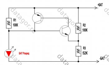
Rice. 8.
Any low-power transistors. The LED ignition voltage is selected by a divider from resistors R2 and R3. It is better to connect the circuit after the protection unit so that the LED does not drain the battery completely.
The nuance of durability
The manufacturer usually claims 300 cycles, but if you charge lithium just 0.1 Volt less, to 4.10 V, then the number of cycles increases to 600 or even more.Operation and Precautions
It is safe to say that lithium-polymer batteries are the most “delicate” batteries in existence, that is, they require mandatory compliance with several simple but mandatory rules, failure to comply with which can cause trouble.1. Charge to a voltage exceeding 4.20 Volts per jar is not allowed.
2. Do not short circuit the battery.
3. Discharge with currents that exceed the load capacity or heat the battery above 60°C is not allowed. 4. A discharge below a voltage of 3.00 Volts per jar is harmful.
5. Heating the battery above 60°C is harmful. 6. Depressurization of the battery is harmful.
7. Storage in a discharged state is harmful.
Failure to comply with the first three points leads to a fire, the rest - to complete or partial loss of capacity.
From the experience of many years of use, I can say that the capacity of batteries changes little, but the internal resistance increases and the battery begins to work less time at high current consumption - it seems that the capacity has dropped.
For this reason, I usually install a larger container, as the dimensions of the device allow, and even old cans that are ten years old work quite well.
For not very high currents, old cell phone batteries are suitable.

You can get a lot of perfectly working 18650 batteries out of an old laptop battery.
Where do I use lithium batteries?
I converted my screwdriver and electric screwdriver to lithium a long time ago. I don't use these tools regularly. Now, even after a year of non-use, they work without recharging!I put small batteries in children's toys, watches, etc., where 2-3 “button” cells were installed from the factory. Where exactly 3V is needed, I add one diode in series and it works just right.
I put them in LED flashlights.
Instead of the expensive and low-capacity Krona 9V, I installed 2 cans in the tester and forgot all the problems and extra costs.
In general, I put it wherever I can, instead of batteries.
Where do I buy lithium and related utilities
For sale. At the same link you will find charging modules and other useful items for DIYers.The Chinese usually lie about the capacity and it is less than what is written.

Honest Sanyo 18650
Today, many users have accumulated several working and unused lithium batteries that appear when replacing mobile phones with smartphones.

When using batteries in phones with their own charger, thanks to the use of specialized chips for charge control, there are practically no problems with charging. But when using lithium batteries in various homemade products, the question arises of how and with what to charge such batteries. Some people think that lithium batteries already contain built-in charge controllers, but in fact they have built-in protection circuits, such batteries are called protected batteries. The protection circuits in them are designed mainly to protect against deep discharge and overvoltage when charging above 4.25V, i.e. This is an emergency protection, not a charge controller.
Some “do-it-yourselfers” on the site will immediately write that for little money you can order a special board from China, with which you can charge lithium batteries. But this is only for “shopping” lovers. There is no point in buying something that can be easily assembled in a few minutes from cheap and common parts. We must not forget that you will have to wait about a month for the ordered board. And a purchased device does not bring as much satisfaction as a home-made one.
The proposed charger can be replicated by almost anyone. This scheme is very primitive, but completely copes with its task. All that is required for high-quality charging of Li-Ion batteries is to stabilize the output voltage of the charger and limit the charge current.
The charger is reliable, compact and highly stable output voltage, and, as you know, for lithium-ion batteries this is a very important characteristic when charging.
Charger circuit for li-ion battery
The charger circuit is made using an adjustable voltage stabilizer TL431 and a medium power bipolar NPN transistor. The circuit allows you to limit the battery charging current and stabilizes the output voltage.

Transistor T1 acts as a regulating element. Resistor R2 limits the charging current, the value of which depends only on the battery parameters. It is recommended to use a 1 W resistor. Other resistors may be 125 or 250 mW.
The choice of transistor is determined by the required charging current set to charge the battery. For the case under consideration, charging batteries from mobile phones, you can use domestic or imported NPN transistors of medium power (for example, KT815, KT817, KT819). If the input voltage is high or a low power transistor is used, the transistor must be installed on a radiator.
LED1 (highlighted in red in the diagram) serves to visually indicate battery charge. When you turn on a discharged battery, the indicator glows brightly and dims as it charges. The indicator light is proportional to the battery charge current. But it should be taken into account that if the LED is completely extinguished, the battery will still be charged with a current of less than 50mA, which requires periodic monitoring of the device to prevent overcharging.
To increase the accuracy of monitoring the end of the charge, an additional option for indicating the battery charge (highlighted in green) on the LED2, low-power PNP transistor KT361 and current sensor R5 has been added to the charger circuit. The device can use any type of indicator depending on the required accuracy of battery charge monitoring.
The presented circuit is intended to charge only one Li-ion battery. But this charger can also be used to charge other types of batteries. You only need to set the required output voltage and charging current.
Making a charger
1. We purchase or select from those available, components for assembly in accordance with the diagram.
2. Assembling the circuit.
To check the functionality of the circuit and its settings, we assemble the charger on the circuit board.

The diode in the battery power circuit (negative bus - blue wire) is designed to prevent the lithium-ion battery from discharging in the absence of voltage at the charger input.
3. Setting the output voltage of the circuit.
We connect the circuit to a power source with a voltage of 5...9 volts. Using trimmer resistance R3, we set the output voltage of the charger within 4.18 - 4.20 volts (if necessary, at the end of the adjustment we measure its resistance and install a resistor with the required resistance).
4. Setting the charging current of the circuit.
Having connected a discharged battery to the circuit (as indicated by the LED turning on), we use resistor R2 to set the charging current value using the tester (100...300 mA). If the resistance R2 is less than 3 ohms, the LED may not light up.
5. Prepare the board for mounting and soldering parts.
We cut the required size from the universal board, carefully process the edges of the board with a file, clean and tin the contact tracks.

6. Installation of the debugged circuit on the working board
We transfer the parts from the circuit board to the working one, solder the parts, and make the missing connections using a thin mounting wire. Upon completion of assembly, we thoroughly check the installation.
You can familiarize yourself with the charger circuit, which is perfect for lithium Li-Ion batteries.
At first, its author wanted to present a simple version on the lm317 chip, but in this case, charging must be powered from a higher voltage than 5 volts. The reason is that the difference between the input and output voltages of the lm317 microcircuit must be at least 2 Volts. The voltage of a charged lithium-ion battery is approximately 4.2 Volts. Therefore, the voltage difference is less than 1 volt. And this means that we can come up with another solution.
On AliExpress you can buy a specialized board for charging lithium batteries, which costs about a dollar. Yes, that's true, but why buy something that can be done in a couple of minutes. Moreover, it takes a month until you receive the order. But if you decide to buy a ready-made one so you can use it right away, buy it in this Chinese store. In the store search, enter: TP4056 1A
The simplest scheme
Today we’ll look at options for a UDB charger for lithium batteries that anyone can replicate. The scheme is the simplest one you can think of.
Solution

This is a hybrid circuit where there is voltage stabilization and battery charging current limitation.
Description of charging operation
Voltage stabilization is based on the rather popular tl431 adjustable zener diode microcircuit. Transistor as an amplifying element. The charge current is set by resistor R1 and depends only on the parameters of the battery being charged. This resistor is advised with a power of 1 watt. And all other resistors are 0.25 or 0.125 watts.
As we know, the voltage of one can of a fully charged lithium-ion battery is about 4.2 Volts. Therefore, at the output of the charger we must set exactly this voltage, which is set by selecting resistors R2 and R3. There are many online programs for calculating the stabilization voltage of the tl431 microcircuit.
For the most accurate adjustment of the output voltage, it is recommended to replace resistor R2 with a multi-turn resistance of about 10 kilo-ohms. By the way, such a solution is possible. We use an LED as a charge indicator; almost any LED, color to your taste, will do.
The whole setup comes down to setting the output voltage to 4.2 volts.
A few words about the tl431 zener diode. This is a very popular microcircuit, do not confuse it with transistors in a similar package. This microcircuit is found in almost any switching power supply, for example a computer, where the microcircuit is most often found in the harness.
The power transistor is not critical; any reverse conduction transistor of medium or high power is suitable, for example, from the Soviet ones, KT819, KT805 are suitable. Of the less powerful KT815, KT817 and any other transistors with similar parameters.
What batteries is the device suitable for?
The circuit is designed to charge only one can of a lithium battery. You can charge standard 18 650 batteries and other batteries, you just need to set the appropriate voltage at the output of the charger.
If suddenly for some reason the circuit does not work, then check the presence of voltage at the control pin of the microcircuit. It must be at least 2.5 Volts. This is the minimum operating voltage for the chip's external reference voltage. Although there are versions where the minimum operating voltage is 3 Volts.
It is also advisable to build a small test bench for the specified chip to check its functionality before soldering. And after assembly, we carefully check the installation.
In another publication there is material about improvement.
