Procedure for programming avr microcontrollers. Advice for novice microcontroller programmers. Required set of programs
So, we sorted out the work of the kernel regarding transitions and addressing. It's time to turn our attention to another area - memory.
There are two types of it (EEPROM does not count since it is generally a peripheral, but more about it later):
- RAM - RAM
- ROM - ROM, aka flash, aka program memory
Since our architecture is Harvard, the operative has its own addressing, and the flash has its own. In the datasheet you can see the RAM addressing structure.
Pay attention to the addresses right away! RON and peripheral registers, as well as RAM are located in the same address space. Those. addresses from 0000 to 001F occupy our registers, then up to address 005F there are I/O cells - ports. Through the ports, everything that is on board the controller is configured. And only then, from address 0060 comes our RAM, which we can use for its intended purpose.
Moreover, please note that the I/O registers also have their own addressing - the address space of the I/O registers (from 00 to 3F), it is indicated on the left side of the figure. IO/Register Block This addressing ONLY works in OUT and IN instructions. This leads to an interesting feature.
Peripheral registers can be accessed in two different ways:
- Via IN/OUT commands at a short address in the I/O address space
- Through a group of LOAD/STORE commands at a full address in the RAM address space
Example. Let's take the input register of the asynchronous transceiver UDR; it has the address 0x0C (0x2C); the address in the general address space is indicated in brackets.
LDI R18.10; We loaded the number 10 into register R18. Just like that OUT UDR,R18 ; Deduced in the first way, the compiler itself; Substitutes the value 0x0C instead of UDR STS 0x2C,R18 ; They took me out the second way. Via the Store command; By entering the address directly.
Both methods give identical results. BUT! Those that work by addressing in the input/output space (OUT/IN) are two bytes shorter. This is understandable - they do not need to store the double-byte address of an arbitrary memory cell, and the short address of the input-output space fits into the double-byte instruction code.
True, there is another joke here. The fact is that every year more and more stones from AVR appear and there is more and more meat in them. And each crackling needs its own peripheral I/O registers. And now, we’ve come to the conclusion that the ATMega88 (which replaced the Mega8) already has so many peripherals that its I/O registers no longer fit into the 3F address space limit.
Oops, they've arrived. And this is where those who switch from old stones to new ones begin to express puzzled expressions - why do the OUT/IN commands work on some peripheral registers, but not on others?
And it’s simple - there wasn’t enough bit capacity.
But the core is one, it can no longer be remade. And here the ATMEL people acted cunningly - they introduced the so-called memory mapped registers. Those. all those registers that did not fit into the 3F limit are now available in only one way - through Load/Store.
What a joke. If you open some m88def.inc, then you can see which of the I/O registers are “correct” and which are memory mapped.
There will be something like this:
; ***** I/O REGISTER DEFINITIONS ************************************************ * ; NOTE: ; Definitions marked "MEMORY MAPPED" are extended I/O ports ; and cannot be used with IN/OUT instructions .equ UDR0 = 0xc6 ; MEMORY MAPPED .equ UBRR0L = 0xc4 ; MEMORY MAPPED .equ UBRR0H = 0xc5 ; MEMORY MAPPED .equ UCSR0C = 0xc2 ; MEMORY MAPPED .equ UCSR0B = 0xc1 ; MEMORY MAPPED .equ UCSR0A = 0xc0 ; MEMORY MAPPED blah blah blah, and much more.equ OSCCAL = 0x66 ; MEMORY MAPPED .equ PRR = 0x64 ; MEMORY MAPPED .equ CLKPR = 0x61 ; MEMORY MAPPED .equ WDTCSR = 0x60 ; MEMORY MAPPED .equ SREG = 0x3f ;<------ А тут пошли обычные.equ SPL = 0x3d .equ SPH = 0x3e .equ SPMCSR = 0x37 .equ MCUCR = 0x35 .equ MCUSR = 0x34 .equ SMCR = 0x33 .equ ACSR = 0x30
These are the pies.
And in this field you understand that a large furry organ is flying towards the cross-model compatibility of assembly code with the goal of tightly covering it. After all, it’s one thing to correct all sorts of macro definitions and definitions that describe registers, and another to sit and, like Cinderella, separate the right ports from the wrong ones.
However, there is a solution. Macrolanguage! Don't like the command system? Make up your own with blackjack and whores!
Let's build our own team UOUT, like a universal OUT
Similarly for the IN command. In general, with such macros you can VERY greatly diversify the assembler, turning it into a powerful programming language that can tear apart all sorts of C and Pascal like a rag.
Well, what am I talking about... about RAM.
So, we sorted out the addressing. Now you know where to look for the memory addresses where user RAM cells start - in the datasheet, Memory Map section. But there for reference to know.
And in our code the RAM starts with the directive.DSEG Remember our template?
Include "m16def.inc" ; We use ATMega16 ;= Start macro.inc ============================== ; Macros here;= End macro.inc ================================= ; RAM ============================================================= .DSEG ; RAM segment; FLASH =========================================================== .CSEG ; Code segment; EEPROM ========================================================= .ESEG ; EEPROM segment
After .DSEG we can set our variables. And here we simply have a burst of cells - occupy any one. Enter the address and be happy. But why count addresses manually? Let the compiler think here.
Therefore, we will take and set a label
0x0060 ## ;Variables 0x0061 ## 0x0062 ## 0x0063 ## ;Variables2 0x0064 ## 0x0065 ## ;Variables4 could start here
As ## any byte. By default FF. Of course, there is no need to talk about any typing of variables, initial initialization, overflow control and other bourgeois joys. This is Sparta! I mean, assembler. All by hand.
If we draw an analogy with C, then it’s like working with memory through void pointers alone. Sishniks will understand. They will understand and be horrified. Because this world is cruel and treacherous. I miscalculated the index a little and lost other data. And damn you will catch this error if it doesn’t pop up right away.
So attention, attention and attention again. We run all memory operations through tracing and nothing will fail or overflow.
The .ORG directive also works in the data segment. It works exactly the same way - it transfers addresses, in this case marks, from here to the end of memory. Just one subtlety - ORG 0000 will give us the very beginning of the RAM, and this is R0 and other registers. And zero kilometer of RAM using Mega16 as an example will give ORG 0x0060. And in other controllers there is some other value. It’s lazy to go through the datasheet every time, so there is such a macro definition as SRAM_START, which indicates the start of RAM for a specific MK.
So if we want the beginning of the RAM, say 100 bytes, to be left under some kind of garbage buffer, then we do this trick.
| 1 2 3 4 | .DSEG .ORG SRAM_START+100 Variables: .byte 3 |
DSEG .ORG SRAM_START+100 Variables: .byte 3
Done, we cleared our buffer zone from the beginning to 100.
Okay, we've sorted out the addressing. How to work with memory cells? And for these purposes there are two groups of commands. LOAD and STORE are the largest group of commands.
The fact is that nothing can be done with a RAM cell other than loading a byte into it from RON, or unloading a byte from it into RON.
Store (ST**) commands are written to RAM, and Load (LD**) commands are read.
Reading goes to register R16…R31, and the cell address is specified either directly in the command. Here's a simple example. There is a three-byte Variables variable, it must be increased by 1. That is. perform Variables++ operation
DSEG Variables: .byte 3 Variables2: .byte 1 .CSEG ; The variable is in memory; first you need to get it. LDS R16, Variables ; Read the first Variables byte in R16 LDS R17, Variables+1 ; Read the second Variables byte in R17 LDS R18, Variables+2 ; Well, the third byte in R18; Now let's add 1 to it, because AVR cannot add with a constant, only; to subtract, you have to distort. However, it does not cause any particular problems. SUBI R16,(-1) ; in general, SUBI is a subtraction, but -(- gives + SBCI R17,(-1) ; And here the transfer is taken into account. But more on that later. SBCI R18,(-1) ; Mathematics in assembler is a different story STS Variables, R16 ; Save everything is as it was. STS Variables+1,R17 STS Variables+2,R18
Or you can use another method. Indirect recording via index register.
DSEG Variables: .byte 3 Variables2: .byte 1 .CSEG ; Take the address of our variable LDI YL,low(Variables) LDI YH,High(Variables) ; The variable is in memory; first you need to get it. LD R16, Y+ ; Read the first Variables byte in R16 LD R17, Y+ ; Read the second Variables byte in R17 LD R18, Y+ ; Well, the third byte in R18; Now let's add 1 to it, because AVR cannot add with a constant, only; to subtract, you have to distort. However, it does not cause any particular problems. SUBI R16,(-1) ; actually SUBI is a subtraction, but -(- gives + SBCI R17,(-1) ; And here the transfer is taken into account. But more on that later. SBCI R18,(-1) ; Mathematics in assembler is a different story ST -Y,R18 ; We keep everything as it was. ST -Y,R17 ; But in reverse order ST -Y,R16
Operations with post-increment and pre-decrement are already used here. In the first, we first read, then add 1 to the address. In the second, we first subtract 1 from the address, and then save.
It is convenient to use such incremental commands to iterate through arrays in memory or tables.
And there is also an indirect relative write/read LDD/STD and other options for all three types of indexes (X,Y,Z). In general, smoke the datasheet and command system.
Stack
Oh, the stack is a great thing. What I love about it is that stack disruption turns a working program into a complete mess. Because stack operations require increased attention, because if a stack is broken somewhere and you can’t track it right away, you’ll catch it later... In general, it’s a beauty, not a gizmo.
Why do I love you? Well, if C is a stupid craft, fast and effective, then Assembly is a filigree art. How maniacs like Jim rivet masterpieces from paper and only from paper, although it would seem that you could buy a ready-made prefabricated model and glue for your own pleasure. So here too - the process itself is overwhelming. Including from the hassle of debugging :))))
So, about the stack. What it is? And this is the memory area. Works on the principle of a stack. Those. The last one he put down, he took the first one.
The stack has a pointer that points to the top of the stack. A special register SP is responsible for the stack pointer, or rather it is a register pair SPL and SPH. But in microcontrollers with a small amount of RAM, for example in Tini2313, there is only SPL
When the controller starts, usually the first thing they do is initialize the stack, writing in SP the address of its bottom, from where it will grow. Usually this is the end of the RAM, and it grows towards the beginning.
This is done this way, at the very beginning of the program:
| 1 2 3 4 5 | LDI R16,Low(RAMEND) OUT SPL,R16 LDI R16,High(RAMEND) OUT SPH,R16 |
LDI R16,Low(RAMEND) OUT SPL,R16 LDI R16,High(RAMEND) OUT SPH,R16
Where RAMEND is a macro definition indicating the end of RAM in the current MK.
That's it, the stack is ready to go. Data is pushed onto the stack using the PUSH Rn command, and retrieved via POP Rn.
Rn is any of the RON.
The commands CALL, RCALL, ICALL, RET, RETI and calling an interrupt also work with the stack, but more on that later.
Let's play with the stack to feel how it works, to understand how and where it moves.
Enter the following code into the studio:
CSEG; LDI code segment R16,Low(RAMEND) ; Stack initialization OUT SPL,R16 LDI R16,High(RAMEND) OUT SPH,R16 LDI R17,0 ; Loading values LDI R18.1 LDI R19.2 LDI R20.3 LDI R21.4 LDI R22.5 LDI R23.6 LDI R24.7 LDI R25.8 LDI R26.9 PUSH R17 ; We put the values on the stack PUSH R18 PUSH R19 PUSH R20 PUSH R21 PUSH R22 PUSH R23 PUSH R24 PUSH R25 PUSH R26 POP R0 ; Pop values from the stack POP R1 POP R2 POP R3 POP R4 POP R5 POP R6 POP R7 POP R8 POP R9
Now run the studio step by step and watch how the SP changes. Stack Pointer can be seen in the studio in the same place as Program Counter.
First, we initialize the stack and load the registers with data. The result will be the following picture:
Next, using the POP command, we retrieve data from the stack. Please note that it doesn’t matter to us where we put the data on the stack and where we load it. The main thing is the order of installation! We put it in from the higher registers, and will get it in the lower ones. This will increase the stack pointer.
PUSH R16 PUSH R17 POP R16 POP R17
For example, I already talked about the limitation of lower RONs - they do not allow you to write a number directly into yourself. Only through the registers of the senior group. But this is inconvenient!
The problem is solved using a macro. I called it LDIL - LDI low
MACRO LDIL PUSH R17; Let's save the value of one of the higher registers onto the stack. LDI R17,@1 ; Let's load our immediate value MOV @0,R17 into it; Let's transfer the value to the register of the low group. POP R17; Let's restore the value of the highest register from the stack. .ENDM
Now you can easily use our homemade command.
| 1 | LDIL R0.18 |
Over time, the file with macros acquires such homemade commands and working becomes easy and pleasant.
Stack errors
The stack grows towards the data, and now imagine that we have a State variable in memory and it is located at the address, for example, 0x0450. Dangerously close to the top of the stack. The variable stores, for example, the state of the finite state machine on which the further logic of the program depends. Let's say if there are 3, then we go do one thing, if there are 4 then something else, if there are 5 then something else and so on up to 255 states. And according to the logic of work, after 3 there should be 4re, but not 10
And then there was 3. And then, at one terrible moment, the conditions coincided so much that the stack grew and its top reached this variable, entering a value there, say 20, and then the greyhound fell back. Leaving the muck behind is a classic example of stack overflow. And the logic of the program completely collapsed because of this.
Or the opposite example - the stack was pushed up to the variables, but at that moment the variables were updated and overwrote the stack data. As a result, something wrong was removed from the stack (usually crooked return addresses) and the program crashed. This option, by the way, is much more harmless, because... in this case, the jamb is visible immediately and it does not pop up SUDDENLY after God knows how long.
Moreover, this error may appear and disappear. Depending on how the program works and how deep it loads the stack. However, such a bummer is more common when you write in C, where you can’t see how actively working with the stack is going on. On ASMA everything is much more transparent. And here this can arise due to a frankly crooked algorithm.
Assemblers often encounter other stack errors. First of all, forgetfulness. I put something in and forgot to take it out. If the problem was in a subroutine or an interrupt, then the return address is distorted (more on that a little later), the stack is torn off and the program instantly collapses. Or inattention - I saved the data in one order and retrieved it in another. Oops, the contents of the registers have been exchanged.
To avoid such errors, you need, first of all, to monitor the stack, and secondly, to correctly plan the placement of variables in memory. Keeping the most critical areas and variables (such as state machines or program logic flags) away from the top of the stack, closer to the beginning of memory.
Some people will think that they can take the stack and place it not at the very end of the RAM, but somewhere closer, leaving behind it a pocket for critical data. Not really a good idea. The fact is that the stack can be pushed both downwards using the PUSH command and upwards using the POP commands. The second, although it happens much less often, because... This is more a sin of crooked hands than a cumbersome algorithm, but it also happens.
But the main thing is that the stack itself is a very important structure. The entire mechanism of subroutines and functions rests on it. So a stack failure is an emergency in any case.
Stack perversions
My favorite topic. =)))) Despite the fact that the stack pointer itself is calculated during the PUSH and POP commands, no one is stopping us from picking it out of the SP and using its values to manually calculate the address of the data lying on the stack. Or correct the stack data as we please.
For what? Well, you can find a lot of applications if you strain your brain and start thinking outside the box :))))
Plus, parameters are passed through the stack in classic C and Pascal on the x86 architecture and local variables work. Those. Before calling a function, first all variables are pushed onto the stack, and then, after calling the function, bytes of future local variables are pushed onto the stack.
Then, using SP as a reference point, we can treat these variables as we please. And when the stack is freed with the POP command, they are annihilated, freeing up memory.
In AVR, everything is somewhat different (apparently due to the small amount of memory, where you can’t really push into the stack, but there is a lot of RON), but you can also try to use this mechanism.
True, this already resembles neurosurgery. I made a slight mistake and the patient is dead.
Thanks to the stack and RAM, you can get by with just two or three registers, without much stress about their lack.
Flash memory
EEPROM memory is small, just a few bytes, and sometimes you need to save a lot of data, for example, a message to aliens or a table of sines, so as not to waste time on calculating it. You never know what needs to be stored in memory in advance. Therefore, data can be stored in program memory, in the same kilobytes of flash that the controller has on board.
We’ll write it down, but how can we get it? To do this, you first need to put something there.
Therefore, add a label at the end of the program, within the .CSEG segment, for example, data, and after it, using the .db operator, enter your data.
The DB operator means that we use a byte for each constant. There are also operators that specify double-byte constants DW (as well as DD and DQ).
| 1 | data: .db 12,34,45,23 |
data: .db 12,34,45,23
Now, the data label points to the address of the first byte of the array, the remaining bytes are located by offset, simply adding one to the address.
One subtlety is that the compiler substitutes the mark address, and it considers it the jump address for the program counter. And he, if you remember, addresses double-byte words - after all, the length of the command can be either 2 or 4 bytes.
And our data is byte-by-byte and when accessing it, the controller also addresses it byte-by-byte. The address in words is twice as small as the address in bytes, and this must be taken into account when multiplying the address by two.
To load data from program memory, use the command from the Load Program Memory group
For example, LPM Rn,Z
It enters into register Rn the number from the cell pointed to by register pair Z. Let me remind you that Z is two registers, R30 (ZL) and R31 (ZH). The low byte of the address is entered into R30, and the high byte into R31.
In code it looks like this:
LDI ZL,low(data*2) ; We enter the low byte of the address into the register pair Z LDI ZH,high(data*2) ; We enter the high byte of the address into the register pair Z; multiplication by two is due to the fact that the address is indicated in; in double-byte words, but we need them in bytes. ; Therefore, we multiply by two; After loading the address, you can load the number from the memory LPM R16, Z; in register R16 after this command there will be the number 12, ; taken from program memory. ; somewhere at the end of the program, but in the .CSEG data segment: .db 12,34,45,23
Now that we are already familiar with some of the capabilities and functions of microcontrollers, a logical question naturally arises: what is needed to program microcontrollers? What programs and devices are needed, and where can I get them?

In order for a microcontroller to solve problems and perform certain functions, it must be programmed, that is, a program or program code must be written into it.
Structure and order of writing a program
First of all, before you start writing any program, or rather program code, you should clearly understand what functions the microcontroller will perform. Therefore, you first need to determine the ultimate goal of the program. When it is defined and completely understood, then an algorithm for the program is drawn up. An algorithm is a sequence of command execution. The use of algorithms allows you to more clearly structure the process of writing code, and when writing complex programs, it often allows you to reduce the time spent on their development and debugging.
The next step after compiling the algorithm is directly writing the program code. Programs for microcontrollers are written in the language Si or assembler . Only Assembly is more of a set of instructions than a programming language and is a low-level language.

We will write programs in C, which is a high-level language. Programs in C are written much faster compared to similar programs in Assembly. In addition, all complex programs are written primarily in C.
Here we will not compare the advantages and disadvantages of writing programs in Assembly and C. Over time, having gained some experience in MK programming, you will draw useful conclusions for yourself.
The program code itself can be written in any standard text editor, for example, Notepad. However, in practice they use more convenient editors, which will be discussed below.
Compiling a program
The C code we wrote is not yet understandable to the microcontroller, since the MK understands commands only in the binary (or hexadecimal) system, which is a set of zeros and ones. Therefore, the C code needs to be converted into zeros and ones. For this purpose, a special program is used, called compiler, and the process itself code transformation is called compilation.
To flash the MK firmware, a device called programmer. Depending on the type of programmer, its input is connected to a COM or USB port, and its output is connected to certain pins of the microcontroller.

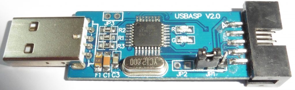
There is a wide selection of programmers and development boards, but we are quite happy with the simplest one programmer, which in China costs no more than $3.
After the microcontroller is flashed, the program is debugged and tested on a real device or, as they also say, on hardware.
Now let's summarize the steps of programming microcontrollers.

When writing simple programs, you can do without the second point, i.e., without drawing up an algorithm on paper; it is enough to keep it in your head.
It should be noted that debugging and testing of the program is also performed before flashing the MK firmware.
Required set of programs
There are many useful and convenient programs for programming MK. They are both paid and free. Among them there are three main ones:
1) Atmel Studio
2) CodeVisionAVR
3) WinAVR
All of these programs are related to IDE – I integrated D development E nvironment – integrated development environment. You can write code in them, compile and debug it.
You should pay attention to Code Vision AVR. This IDE makes writing code easier and faster. However, the program is paid.
At the initial stage of programming, it is better to write all programs manually, without any simplifications. This will help you quickly acquire the necessary skills, and in the future you can well understand and edit codes written by someone else to suit your needs. Therefore, I recommend using Atmel Studio. Firstly, it is absolutely free and constantly updated, and secondly, it was developed by a company that manufactures microcontrollers on which we will learn to program.
Firmware and program debugging
We will flash microcontrollers using an additional program.
If a microcontroller is not available, then its operation can be emulated using the program. It greatly simplifies the process of debugging a program even if you have a microcontroller, so you don’t have to reflash it often, because any microcontroller has a finite number of rewrites, although this number is quite large.
When flashing and debugging the MK, it is convenient to place it on a breadboard, but this is not at all necessary. Therefore, for greater convenience, a breadboard is also useful. There is a large selection of breadboards, but I recommend that you take the one that has as many holes as possible. Once we start connecting seven-segment displays, you'll begin to appreciate the benefits of larger breadboards.
Another important element that will be useful to us is the technical documentation for the MK, called datasheet. In general, you need to download datasheet for ATmega8 microcontroller.
So, what is a microcontroller (hereinafter referred to as MK)? This is, relatively speaking, a small computer housed in a single integrated circuit. It has a processor (arithmetic logic unit, or ALU), flash memory, EEPROM memory, many registers, I/O ports, as well as additional bells and whistles such as timers, counters, comparators, USARTs, etc. After power is applied, the microcontroller boots up and begins executing the program stored in its flash memory. At the same time, it can control a wide variety of external devices via I/O ports.
What does this mean? This means that in the MK you can implement any logical circuit that will perform certain functions. This means that the MK is a microcircuit, the internal contents of which, in fact, we create ourselves. This allows, having bought several completely identical MKs, to assemble completely different circuits and devices on them. If you want to make any changes to the operation of an electronic device, you will not need to use a soldering iron; you will only need to reprogram the MK. In this case, you don’t even need to remove it from your device if you are using an AVR, since these MKs support in-circuit programming. Thus, microcontrollers bridge the gap between programming and electronics.
AVRs are 8-bit microcontrollers, i.e. their ALU can perform simple operations with only 8-bit numbers in one clock cycle. Now it's time to talk about which MK we will use. I'm working with an ATMega16 MK. It is very common and can be purchased in almost any radio parts store for about 100 rubles. If you don’t find it, then you can buy any other MK of the MEGA series, but in this case you will have to look for documentation for it, since the same “legs” of different MKs can perform different functions, and by connecting, it would seem, If all the conclusions are correct, you may get a working device, or maybe just a cloud of stinking smoke. When purchasing an ATMega16, make sure that it comes in a large 40-pin DIP package, and also buy a socket for it into which it can be inserted. To work with it, you will also need additional devices: LEDs, buttons, connectors, etc.
ATMega16 has a very large number of diverse functions. Here are some of its characteristics:
- Maximum clock frequency – 16 MHz (8 MHz for ATMega16L)
- Most commands are executed in one clock cycle
- 32 8-bit working registers
- 4 full 8-bit I/O ports
- two 8-bit timer/counters and one 16-bit
- 10-bit analog-to-digital converter (ADC)
- internal clock generator at 1 MHz
- analog comparator
- interfaces SPI, I2C, TWI, RS-232, JTAG
- in-circuit programming and self-programming
- pulse width modulation (PWM) module

Full characteristics of this device, as well as instructions for their use, can be found in the reference book (Datasheet) for this MK. True, it is in English. If you know English, be sure to download this Datasheet, it contains a lot of useful information.
Let's finally get down to business. I recommend making a special development and debugging board for the microcontroller, on which you can assemble any electrical circuit with a microcontroller without a soldering iron (or almost without it). Using such a board will greatly facilitate working with the MK and speed up the process of learning its programming. It looks like this:

What will you need for this?

First, you will need the board itself. I bought a ready-made one at a radio parts store for 115 rubles. Then I soldered all the necessary parts to it. The result is an incredibly convenient thing, on which you can assemble any electrical circuit in a matter of minutes by connecting cables and installing microcircuits and indicators.

To connect circuit elements, it is very convenient to use cables with connectors at the ends. These connectors are put on the “legs” sticking out next to each port of the MK. The microcontroller should be installed in the socket, and not soldered to the board, otherwise it will be very difficult to remove it if you accidentally burn it. Below is the pinout of the ATMEGA16 MK:

Let us explain which legs we are interested in now.
- VCC - power is supplied here (4.5 - 5.5 V) from a stabilized source
- GND – ground
- RESET – reset (at low voltage level)
- XTAL1, XTAL2 – a quartz resonator is connected here
- PA, PB, PC, PD – input/output ports (A, B, C and D, respectively).
Anything that produces 7-11 V DC can be used as a power source. For stable operation of the MK, a stabilized power supply is required. As a stabilizer, you can use 7805 series microcircuits. These are linear integrated stabilizers, the input of which is supplied with 7-11 V of direct unstabilized current, and the output is 5 V of stabilized current. Before and after 7805, you need to install filter capacitors (electrolytic for filtering low-frequency interference and ceramic for high-frequency). If you cannot find a stabilizer, then you can use a 4.5 V battery as a power source. The MK must be powered directly from it.
Below is a diagram of the MK connection:

Let's now figure out what's what here.
BQ1 is a quartz resonator that sets the operating frequency of the MK. You can set any up to 16 MHz, but since we plan to work in the future with a COM port, I recommend using resonators for the following frequencies: 14.7456 MHz, 11.0592 MHz, 7.3725 MHz, 3.6864 MHz or 1 ,8432 MHz (later it will become clear why). I used 11.0592 MHz. It is clear that the higher the frequency, the higher the speed of the device.
R1 is a pull-up resistor that maintains a voltage of 5 V at the RESET input. A low voltage level on this input indicates a reset. After the reset, the MK boots up (10 - 15 ms) and starts executing the program again. Since this is a high-impedance input, you cannot leave it “dangling in the air” - a small pickup on it will lead to an unexpected reset of the MK. This is exactly what R1 is for. For reliability, I also recommend installing capacitor C6 (no more than 20 µF).
SB1 – reset button.
The quartz resonator and filter capacitor C3 should be located as close as possible to the MK (no further than 5-7 cm), since otherwise interference may occur in the wires, leading to malfunctions of the MK.
The blue rectangle in the diagram outlines the programmer itself. It is convenient to make it in the form of a wire, one end of which is plugged into the LPT port, and the other into a certain connector next to the MK. The wire should not be excessively long. If problems arise with this cable (usually they don’t, but anything can happen), you will have to solder the Altera ByteBlaster adapter. How to do this is written in the description of the AVReal programmer.
Now that we've dealt with the hardware, it's time to move on to the software.
There are several development environments for AVR programming. Firstly, this is AVR Studio - the official programming system from Atmel. It allows you to write in assembler and debug programs written in assembly, C and C++. IAR is a commercial programming system in C, C++ and assembly language. WinAVR is an open source compiler. AtmanAVR is a programming system for AVR with an interface almost exactly the same as Visual C++ 6. AtmanAVR also allows you to debug programs and contains many helper functions that make writing code easier. This programming system is commercial, but, according to the license, you can use it for free for a month.
I suggest starting to work with IAR as the most transparent development environment. In IAR, a project is created entirely by hand; therefore, having completed several projects, you will already clearly know what each line of code means and what will happen if you change it. When working with AtmanAVR, you will either have to use a pre-created template, which is very cumbersome and difficult to understand for a person without experience, or have a lot of problems with header files when assembling the project from scratch. Having dealt with IAR, we will subsequently look at other compilers.
So, first, get some IAR. It is very common and finding it should not be a problem. After downloading IAR 3.20 from somewhere, install the compiler/working environment and launch it. After this you can start working.
Having launched IAR, select file/new/workspace, select the path to our project and create a folder for it and give it a name, for example, “Prog1”. Now let's create a project: Project / Create new project… Let's also call it “Prog1”. Right-click on the project title in the project tree and select “Options”

Here we will configure the compiler for a specific MK. First, you need to select the ATMega16 processor type on the Target tab, check the Enable bit definitions in I/O-include files checkbox on the Library Configuration tab (so that you can use the bit names of various MK registers in the program code), and select the C library type there /EU++. In the ICCAVR category, you need to check the Enable multibyte support checkbox on the Language tab, and turn off optimization on the Optimization tab (otherwise it will ruin our first program).

Next, select the XLINK category. Here you need to determine the format of the compiled file. Since we are now setting options for the Debug mode, as described in the title, we need to get a debug file as output. Later we will open it in AVR Studio. To do this, you need to select the extension.cof, and the file type is ubrof 7.

Now click OK, then change Debug to Release.

Go to Options again, where all parameters except XLINK are set to the same. In XLINK, change the extension to .hex, and the file format to intel-standart.

That's all. Now you can start writing your first program. Create a new Source/text and enter the following code in it:
#include"iom16.h" short unsigned int i; void main( void) (DDRB = 255; PORTB = 0; while(1) { if(PORTB == 255) PORTB = 0; else PORTB++; for(i=0; iThe file "iom16.h" is located in the folder (C:\Program Files)\IAR Systems\Embedded Workbench 3.2\avr\inc. If you are using another MK, for example, ATMega64, then select the file “iom64.h”. These header files store information about the MK: the names of registers, bits in registers, and the names of interrupts. Each individual pin of port A, B, C, or D can act as either an input or an output. This is determined by the Data Direction Register (DDR). 1 makes the leg an output, 0 an input. Thus, by setting, for example, DDRA = 13, we make the “legs” PB0, PB2, PB3 outputs, the rest - inputs, because 13 in binary is 00001101.
PORTB is a register that determines the state of the port pins. Having written 0 there, we set the voltage at all outputs to 0 V. Then there is an endless loop. When programming the MK, they always make an endless loop in which the MK performs some action until it is reset or until an interruption occurs. In this cycle they write, as it were, “background code”, which the MK executes as the last thing. This could be, for example, displaying information on a display. In our case, the contents of the PORTB register are increased until it is full. After that everything starts all over again. Finally, a ten thousand cycle for loop. It is needed to form a visible delay in switching the state of port B.
Now we save this file in the project folder as Prog1.c, copy the iom16.h file to the project folder, select Project/Add Files and add “iom16.h” and “Prog1.c”. Select Release, press F7, the program compiles and the message should appear:
| Total number of errors: 0 |
| Total number of warnings: 0 |
Here's a photo of my programmer:

Download the AVReal programmer. Copy it (AVReal32.exe) to the Release/exe folder, where the Prog1.hex file should be located. We supply power to the MK, connect the programming cable. Open Far Manager (it is most convenient to flash MK), go to this folder, press Ctrl+O. Since we have a completely new MK, we stuff
avreal32.exe +MEGA16 -o11.0592MHZ -p1 -fblev=0,jtagen=1,cksel=F,sut=1 –w
Don't forget to enter the correct frequency if you are not using 11059200 Hz! At the same time, the so-called fuses – registers that control its operation (use of an internal generator, Jtag, etc.). After this, it is ready to receive the first program. The programmer is given the used LPT port, frequency, file name, and others as parameters (all of them are listed in the description of AVReal). We dial:
Avreal32.exe +Mega16 -o11.0592MHz -p1 -e -w -az -% Prog1.hex
If the connection is correct, the programmer will report successful programming. There is no guarantee that this will work the first time (the first time you call the program). I myself sometimes get programmed the second time. Perhaps the LPT port is faulty or there is interference in the cable. If problems occur, check your cable carefully. From my own experience, I know that 60% of malfunctions are associated with a lack of contact in the right place, 20% with the presence of an unnecessary one, and another 15% with erroneous soldering of the wrong thing to the wrong thing. If all else fails, read the description of the programmer and try building Byte Blaster.

Let's assume everything works for you. If you now connect eight LEDs to port B of the MK (do this with the MK turned off, and it is advisable to include 300-400 Ohm resistors in series with the LEDs) and apply power, a small miracle will happen - a “wave” will run through them!
© Kiselev Roman
May 2007
1. Advantages of the proposed method
Device circuits based on microcontrollers (MCUs) are usually distinguished by a combination of two difficult-to-combine qualities: maximum simplicity and high functionality. In addition, the functionality can be changed and expanded in the future without making any changes to the circuit - just by replacing the program (flashing). These features are explained by the fact that the creators of modern microcontrollers tried to place on one chip everything that a developer of an electronic device could need - at least as much as possible. As a result, there was a shift in emphasis from circuitry and installation to software. With the use of MK, there is now less need to “load” the circuit with parts, and there are fewer connections between components. This, of course, makes the circuit more attractive for repetition by both experienced and novice electronics engineers. But, as usual, you have to pay for everything. This, too, was not without its difficulties. If you buy a new MK, install it in a circuit correctly assembled from serviceable parts and apply power, then nothing will work - the device will not work. The microcontroller needs a program.
It would seem that everything is simple with this too - on the Internet you can find many schemes with free firmware. But here there is one catch: the firmware must somehow be “uploaded” into the microcontroller. For someone who has never done this before, such a task often becomes a problem and the main repulsive factor, often forcing them to abandon the delights of using MK and look for schemes based on “loose” and rigid logic. But everything is not as complicated as it might seem at first glance.
After analyzing publications on the Internet, you can see that this problem is most often solved in one of two ways: buying a ready-made programmer or making a homemade one. At the same time, published circuits of homemade programmers are very often unreasonably complex - much more complex than is really necessary. Of course, if you plan to flash the MK every day, it is better to have a “cool” programmer. But if the need for such a procedure arises infrequently, from time to time, then you can do without a programmer altogether. No, of course, we are not talking about learning to do this with the power of thought. This means that by understanding how the programmer interacts with the microcontroller when writing and reading information in its programming mode, we can make do with available tools for a wider purpose. These tools will have to replace both the software and hardware parts of the programmer. The hardware must provide a physical connection to the MK microcircuit, the ability to apply logical levels to its inputs and read data from its outputs. The software part must ensure the operation of the algorithm that controls all the necessary processes. We also note that the quality of recording information in the MK does not depend on how “cool” your programmer is. There is no such thing as “better recorded” or “worse”. There are only two options: “registered” and “not registered”. This is explained by the fact that the recording process inside the crystal is directly controlled by the MK itself. You just need to provide it with high-quality power (no interference or ripple) and properly organize the interface. If the results of the test reading reveal no errors, then everything is in order - you can use the controller for its intended purpose.
In order to write a program into the MK without having a programmer, we need a USB-RS232TTL port converter and, as well. The USB-RS232TTL converter allows you to use a USB port to create a COM port that differs from the “real” one only in that its inputs and outputs use TTL logical levels, that is, voltage in the range from 0 to 5 volts (you can read more in the article " "). In any case, such a converter is useful to have in your “household,” so if you don’t already have one, it’s definitely worth purchasing. As for the logical levels, in our case TTL is even an advantage over a regular COM port, because the inputs and outputs of such a port can be directly connected to any microcontroller powered by 5 V, including ATtiny and ATmega. But do not try to use a regular COM port - they use voltages in the range from -12 to +12 V (or -15...+15V). In this case, direct connection to the microcontroller is unacceptable!!!
The idea of creating a script for the Perpetuum M program, which implements the functions of the programmer, arose after reading a number of publications on the Internet offering certain solutions for MK firmware. In each case, serious deficiencies or excessive difficulties were discovered. Often I came across programmer circuits that contained a microcontroller, and at the same time, advice was given quite seriously like: “... and to program the microcontroller for this programmer we will need... that’s right - another programmer!” Next, it was suggested to go to a friend, look for a paid service, etc. The quality of the software distributed on the network for these purposes was also not impressive - many problems were noticed both with functionality and with the “cloudiness” of the user interface. It often takes a lot of time to understand how to use a program - it must be studied even to carry out the simplest actions. Another program can do something for a long time and diligently, but the user learns that nothing is being written to the MK only after the entire firmware has been completely completed and subsequent test reading. The following problem also occurs: the user tries to select his MK from the list of supported crystals, but it is not in the list. In this case, you will not be able to use the program - inclusion in the list of missing MKs, as a rule, is not provided. In addition, manually selecting a controller from the list looks strange, considering that the programmer in many cases can itself determine the type of MK. All this is said not in order to throw mud at existing products, but in order to explain the reason for the appearance of the script for the Perpetuum M program, described in this article. The problem really exists, and it concerns primarily beginners who do not always manage to overcome this “wall” in order to take their first step into the world of microcontrollers. The proposed script takes into account the shortcomings found in other programs. Maximum “transparency” of the algorithm’s operation has been implemented, an extremely simple user interface that does not require learning and leaves no chance of getting confused and “clicking the wrong thing.” If the required MK is not among the supported ones, you can add its description yourself, taking the necessary data from the documentation downloaded from the MK developer’s website. And, most importantly, the script is open for study and modification. Anyone can open it in a text editor, study and edit it at their own discretion, changing existing functions to their taste and adding missing ones.
The first version of the script was created in June 2015. This version only provides support for Atmel's ATtiny and ATmega series microcontrollers with functions for writing/reading flash memory, setting configuration bits, and automatically detecting the controller type. Writing and reading EEPROM is not implemented. There were plans to supplement the functionality of the script: add writing and reading EEPROM, implementing support for PIC controllers, etc. For this reason, the script has not yet been published. But due to lack of time, the implementation of the plan was delayed, and so that the best does not become the enemy of the good, it was decided to publish the existing version. If already the implemented functions will not be enough, please do not be upset. In this case, you can try to add the desired function yourself. I will not hide: the idea of creating this script initially also has an educational meaning. Having understood the algorithm and adding something of your own to it, you You will be able to better understand the operation of the MK in programming mode, so that in the future you will not find yourself in the position of a girl in front of a broken down car, thoughtfully looking at its insides and not understanding why it “doesn’t work.”
2. MK interface in programming mode
There are several different ways to put the controller into programming mode and work with it in this mode. The easiest to implement for controllers of the ATtiny and ATmega series is, perhaps, SPI. We will use it.
But, before we begin to consider the signals necessary to generate SPI, we will make a number of reservations. The microcontroller has configuration bits. These are something like toggle switches, switching which allows you to change some properties of the microcircuit in accordance with the needs of the project. Physically, these are non-volatile memory cells, like those into which a program is written. The difference is that there are very few of them (up to three bytes for ATmega), and they are not part of the address space of any memory. Writing and reading configuration data is performed by separate commands in the MK programming mode. Now it is important to note that some configuration bits affect the very ability to use SPI. With some of their values, it may turn out that SPI cannot be used. If you come across such a microcontroller, the method proposed in this article will not help. In this case, you will either have to change the settings of the configuration bits in the programmer, which supports a different programming mode, or use a different microcontroller. But this problem only applies to used MKs, or those with which someone has already unsuccessfully “played around”. The fact is that new MCUs come with configuration bit settings that do not prevent the use of SPI. This is confirmed by the test results of the programmer script for the Perpetuum M program, during which four different MKs (ATmega8, ATmega128, ATtiny13, ATtiny44) were successfully flashed. They were all new. The initial setting of the configuration bits was consistent with the documentation and did not interfere with the use of SPI.
Given the above, you should pay attention to the following bits. The SPIEN bit explicitly allows or denies the use of SPI, therefore in our case its value must be enabling. The RSTDISBL bit is capable of turning one of the outputs of the microcircuit (predetermined) into the input of the “reset” signal, or not turning it (depending on the value written to this bit). In our case, the “reset” input is necessary (if it is absent, it will not be possible to switch the MK to programming mode via SPI). There are also bits of the CKSEL group that specify the source of the clock signal. They do not prevent the use of SPI, but they also need to be kept in mind, because if there are no clock pulses at all, or if their frequency is lower than acceptable for a given SPI speed, nothing good will happen either. Typically, new MCUs that have an internal RC oscillator have the CKSEL group bits configured to use it. This suits us quite well - clocking is provided without any additional effort on our part. There is no need to solder the quartz resonator or connect an external generator. If the specified bits contain a different setting, you will have to take care of clocking in accordance with the setting. In this case, it may be necessary to connect a quartz resonator or an external clock generator to the MCU. But in this article we will not consider how this is done. The examples of connecting an MK for programming contained in this article are designed for the simplest case.
|
Rice. 1. Data exchange via SPI in programming mode |
Now let's turn to Figure 1, taken from the documentation for the ATmega128A MK. It shows the process of transmitting one byte to the MK and simultaneously receiving one byte from the MK. Both of these processes, as we see, use the same clock pulses supplied from the programmer to the microcontroller at its SCK input - one of the pins of the microcircuit, for which such a role is assigned in the SPI programming mode. Two more signal lines provide data reception and transmission one bit per clock cycle. Through the MOSI input, data enters the microcontroller, and read data is taken from the MISO output. Notice the two dotted lines drawn from SCK to MISO and MOSI. They show at what moment the microcontroller “swallows” the data bit set at the MOSI input, and at what moment it itself sets its own data bit to the MISO output. Everything is quite simple. But to enter the MK into programming mode, we still need a RESET signal. Let's also not forget about the common GND wire and VCC power supply. In total, it turns out that only 6 wires need to be connected to the microcontroller to flash its firmware via SPI. Below we will analyze this in more detail, but for now we will add that data exchange with the MK in programming mode via SPI is performed in packets of 4 bytes. The first byte of each packet is basically entirely dedicated to instruction encoding. The second byte, depending on the first, can be a continuation of the command code, or part of the address, or can have an arbitrary value. The third byte is used primarily for transmitting addresses, but can have an arbitrary value in many instructions. The fourth byte usually transmits data or has an arbitrary value. Simultaneously with the transmission of the fourth byte, some commands receive data coming from the microcontroller. Details for each command can be found in the controller documentation in the table called "SPI Serial Programming Instruction Set". For now, we only note that the entire exchange with the controller is built from a sequence of 32-bit packets, in each of which no more than one byte of useful information is transmitted. This is not very optimal, but overall it works well.
3. Connecting the MK for programming
To ensure that all the necessary signals are supplied to the microcontroller inputs to organize the SPI interface and read data from its MISO output, it is not necessary to create a programmer. This can be easily done using the most common USB-RS232TTL converter.
On the Internet you can often find information that such converters are inferior and that nothing serious can be done with them. But with regard to most converter models, this opinion is wrong. Yes, there are converters on sale that do not have all the inputs and outputs available compared to a standard COM port (for example, only TXD and RXD), while having a non-separable design (the microcircuit is filled with plastic - it is impossible to reach its pins). But these are not worth buying. In some cases, you can get the missing port inputs and outputs by soldering the wiring directly to the chip. An example of such an “improved” converter is shown in Figure 2 (chip PL-2303 - more details about the purpose of its pins in the article “”). This is one of the cheapest models, but has its own advantages when used in homemade designs. Full-featured adapter cords with a standard nine-pin connector at the end, like a COM port, are also widespread. They differ from a regular COM port only in TTL levels and incompatibility with legacy software and some older hardware. It can also be noted that the cords on the CH34x chip show themselves to be much more reliable and stable in various extreme tests compared to converters on the PL-2303. However, during normal use the difference is not noticeable.
When choosing a USB-RS232TTL converter, you should also pay attention to the compatibility of its driver with the version of the operating system you are using.
Let's take a closer look at the principle of connecting a microcontroller and a USB-RS232TTL converter using the example of four different MK models: ATtiny13, ATtiny44, ATmega8 and ATmega128. Figure 3 shows the general diagram of such a connection. It may surprise you to know that the RS232 signals (RTS, TXD, DTR and CTS) are being used inappropriately. But don't worry about it: the Perpetuum M program is able to work with them directly - set output values and read input states. In any case, the widely used USB-RS232TTL converters on CH34x and PL-2303 chips provide this capability - this has been verified. There should also be no problems with other popular converters, since standard Windows functions are used to access the port.
The resistors shown in the general diagram can, in principle, not be installed, but it is still better to install them. What is their purpose? Using the TTL inputs and outputs of the converter and the five-volt power supply of the microcontroller, we thereby get rid of the need to coordinate logical levels - everything is already quite correct. This means that the connections can be direct. But during experiments, anything can happen. For example, according to the law of meanness, a screwdriver can fall just in the place where it could not possibly fall, and short-circuit something that in no case should be short-circuited. Of course, anything can turn out to be a “screwdriver”. Resistors in this case sometimes reduce the consequences. one of their purposes is to eliminate a possible output conflict.The fact is that after programming is completed, the microcontroller goes into normal operation mode, and it may happen that its pin connected to the output of the converter (RTS, TXD or DTR) also becomes an output, according to the program just recorded in the MK. In this case, it will be very bad if two directly connected outputs “fight” - try to set different logical levels. In such a “struggle,” someone may “lose,” but we don’t want that.
The values of the three resistors are selected at the level of 4.3 KOhm. This applies to connections between the converter output and the microcontroller input. The accuracy of the resistors does not matter: you can reduce their resistance to 1 KOhm or increase it to 10 KOhm (but in the second case, the risk of interference increases when using long wires on the way to the MK). As for the connection between the converter input (CTS) and the microcontroller output (MISO), a 100 Ohm resistor is used here. This is explained by the peculiarities of the input of the converter used. During the tests, a converter was used on the PL-2303 microcircuit, the inputs of which, apparently, are connected to the power supply positive with a relatively low resistance (of the order of several hundred Ohms). To “break the pull-up” I had to install a resistor with such a small resistance. However, you don’t have to install it at all. On the converter this is always the input. It cannot become a way out, which means there will be no conflict of exits in any development of events.
If the chip has a separate AVCC pin for powering the analog-to-digital converter (for example, ATmega8 or ATmega128), it should be connected to the common VCC power pin. Some ICs have more than one VCC power pin or more than one GND. For example, ATmega128 has 3 GND pins and 2 VCC pins. In a permanent design, it is better to connect pins of the same name to each other. In our case, during programming, you can use one VCC and GND pin each.
And here is what the ATtiny13 connection looks like. The figure shows the pin assignments used when programming via SPI. Next to the photo is what a temporary connection looks like in reality.
Some may say that this is not serious - connections on the wiring. But you and I are sensible people. Our goal is to program the microcontroller, spending a minimum of time and other resources on it, and not to show off in front of someone. The quality does not suffer. The “on wires” method in this case is quite effective and justified. Flashing the controller's firmware is a one-time procedure, so there is no point in covering it with rhinestones. If it is intended to change the firmware in the future without removing the controller from the circuit (in the finished product), then this is taken into account during installation during the manufacture of the device. Usually a connector (RESET, SCK, MOSI, MISO, GND) is installed for this purpose, and the MK can be flashed even after installation on the board. But these are creative delights. We are considering the simplest case.
Now let's move on to the ATtiny44 MK. Everything is pretty much the same here. Based on the drawing and photo, even a beginner will not have any difficulty figuring out the connection. Like the ATtiny44, you can connect the ATtiny24 and ATtiny84 microcontrollers - the pin assignments for these three are the same.
Another example of temporarily connecting a controller for programming it is ATmega8. There are more pins here, but the principle is the same - a few wires, and now the controller is ready to “fill” information into it. The extra black wire in the photo coming from pin 13 does not take part in programming. It is designed to remove a sound signal from it after the MK exits the programming mode. This is due to the fact that during debugging of the script for "Perpetuum M" the music box program was downloaded to the MK.
Often one controller is available in different housings. In this case, the assignment of pins for each case is distributed differently. If the housing of your controller is not similar to the one shown in the figure, check the purpose of the pins in the technical documentation, which can be downloaded from the MK developer’s website.
To complete the picture, let's look at connecting an MK microcircuit with a large number of "legs". The purpose of the extra black wire in the photo coming from pin 15 is exactly the same as in the case of the ATmega8.
You are probably already convinced that everything is quite simple. Anyone who knows how to count the pins of microcircuits (from the mark in a circle counterclockwise) will figure it out. And don't forget about accuracy. Microcircuits love neat people and do not forgive careless treatment.
Before moving on to the software part, make sure that the USB-RS232TTL converter driver is installed correctly (check the Windows Device Manager). Remember or write down the number of the virtual COM port that appears when you connect the converter. This number will need to be entered into the text of the script, which you can read about below.
4. Script - programmer for "Perpetuum M"
We figured out the hardware part of the “programmer”. This is already half the battle. Now it remains to deal with the software part. Its role will be performed by the Perpetuum M program under the control of a script, which implements all the necessary functions for interacting with the microcontroller.
The archive with the script should be unpacked into the same folder where the perpetuum.exe program is located. In this case, when you run the perpetuum.exe file, a menu will be displayed on the screen with a list of installed scripts, among which there will be the line “AVR MK Programmer” (it may be the only one). This is the line we need.
The script is located in the PMS folder in the file "MK Programmer AVR.pms". This file can be viewed, studied and edited if necessary in a regular text editor like Windows Notepad. Before using the script, you will most likely need to make changes to the text related to port settings. To do this, check the name of the port used in Windows Device Manager and, if necessary, make the appropriate amendment to the line "PortName="COM4";" - instead of the number 4 there may be another number. Also, when using a different USB-RS232TTL converter model, you may need to change the signal inversion settings (script lines starting with the word “High”). You can check the inversion of signals by the USB-RS232TTL converter using one of the examples contained in the instructions for the Perpetuum M program (section of functions for working with the port).
The MK_AVR subfolder contains files with descriptions of supported controllers. If the controller you need is not among them, you can add the one you need yourself, following an analogy. Take one of the files as a sample, and using a text editor, enter the necessary data, taking it from the documentation for your microcontroller. The main thing is to be careful, enter the data without errors, otherwise the MK will not be programmed, or will be programmed incorrectly. The original version supports 6 microcontrollers: ATtiny13, ATtiny24, ATtiny44, ATtiny84, ATmega8 and ATmega128. The script implements automatic recognition of the connected controller - no need to specify it manually. If the identifier read from the MK is not among the available descriptions, a message is displayed that the controller could not be recognized.
The archive with the script also contains additional information. The AVR controller inc files folder contains a very useful and extensive collection of controller definition files. These files are used when writing your own programs for MK. Four more folders "MusicBox_..." contain files with a program in Assembly language and firmware ready for downloading to the MK separately for ATtiny13, ATtiny44, ATmega8 and ATmega128. If you have already connected one of these MKs for programming, as suggested in this article, then you can flash it right now - you will get a music box. More on this below.
When you select the line “MK AVR Programmer” in the script menu, the script begins to be executed. At the same time, it opens the port, sends a command to the MK to switch to programming mode, receives confirmation from the MK about the successful transition, requests the MK identifier and searches for a description of this MK by its identifier among the available files with descriptions. If it does not find the required description, it displays a corresponding message. If a description is found, then the main menu of the programmer opens. You can see its screenshot in Figure 8. Further understanding is not difficult - the menu is very simple.
In the first version of the script, some functions of a full-fledged programmer are not implemented. For example, there is no way to read and write to EEPROM. But if you open the script in a text editor, you will see that it is very small in size, despite the fact that the main thing is already implemented in it. This suggests that adding the missing functions is not so difficult - the language is very flexible, it allows you to implement rich functionality in a small program. But for most cases, even the existing functions are enough.
Some functionality limitations are described directly in the script text:
//implemented recording only from the zero address (Extended Segment Address Record is ignored, LOAD OFFSET - too)
//the order and continuity of records in the HEX file is not checked
//checksum is not checked
This applies to working with a HEX file, from which the firmware code for the MK is taken. If this file is not corrupted, checking the checksum will have no effect. If it is distorted, it will not be possible to detect it using the script. In most cases, the remaining restrictions will not hurt, but you still need to keep them in mind.
5. Music box - a simple craft for beginners
If you have one of these microcontrollers: ATtiny13, ATtiny44, ATmega8 or ATmega128, you can easily turn it into a music box or music card. To do this, it is enough to write the corresponding firmware into the MK - one of those four that are located in the "MusicBox_..." folders in the same archive with the script. Firmware codes are stored in files with the extension ".hex". Using ATmega128 for such a craft, of course, is “fatty”, just like ATmega8. But this may be useful for testing or experimentation, in other words, for educational purposes. The texts of the programs in Assembler are also attached. The programs were not created from scratch - the music box program from A.V. Belov’s book “AVR Microcontrollers in Amateur Radio Practice” was taken as a basis. The original program has undergone a number of significant changes:
1. adapted for each of the four MKs: ATtiny13, ATtiny44, ATmega8 and ATmega128
2. buttons have been eliminated - nothing needs to be connected to the controller except power and a sound emitter (melodies are played one after another in an endless loop)
3. the duration of each note is reduced by the duration of the pause between notes to eliminate disturbances in musical rhythm
4. the eighth melody is connected, not used in the book version
5. from the subjective: some “improvements” to optimize and make the algorithm easier to understand
In some melodies one can hear falsehood and even gross errors, especially in “Smile” - in the middle. The ringtone codes were taken from the book (or rather, downloaded from the book’s author’s website along with the original asm file) and have not been modified. Apparently, there are errors in the encoding of the melodies. But this is not a problem - anyone who is “friendly” with music can easily figure it out and fix everything.
In ATtiny13, due to the lack of a 16-bit counter, an 8-bit counter had to be used to reproduce notes, which led to a slight decrease in the accuracy of the notes. But this is hardly noticeable by ear.
About the configuration bits. Their settings must correspond to the state of the new microcontroller. If your MK has been used somewhere before, you need to check the state of its configuration bits, and, if necessary, bring them into line with the settings of the new microcontroller. You can find out the state of the configuration bits of the new microcontroller from the documentation for this MK (section "Fuse Bits"). The exception is ATmega128. This MCU has the M103C bit, which enables compatibility mode with the older ATmega103. Activating the M103C bit greatly reduces the capabilities of the ATmega128, and this bit is active on the new MK. You need to reset the M103C to an inactive state. To manipulate configuration bits, use the corresponding section of the programmer script menu.
There is no point in giving a diagram of the music box: it only contains a microcontroller, power supply and a piezo-sound emitter. Power is supplied in exactly the same way as we did when programming the MK. The sound emitter is connected between the common wire (GND pin of the controller) and one of the MK pins, the number of which can be found in the file with the program assembly code (*.asm). At the beginning of the program text for each MK in the comments there is a line: “the sound signal is generated at pin XX.” When the programmer script is completed, the microcontroller exits the programming mode and goes into normal operation. Playback of melodies begins immediately. By connecting a sound emitter, you can check this. You can leave the sound emitter connected while programming the crystal only if the sound is taken from a pin that is not used in SPI, otherwise the additional capacitance on the pin may interfere with programming.
