How to make a cheap Arduino-based MIDI controller with your own hands. How to make a cheap MIDI controller based on Arduino with your own hands Reading potentiometer positions
I have long wanted to awaken the composer within me and start creating my own electronic music. However, I was (to put it mildly) discouraged by the high prices of MIDI controllers. But after scouring the Internet, I got the idea to create my own controller using Arduino Uno and conductive paints!


Let's start)
Step 1: Selection of parts
You can deviate slightly from the material presented and the MIDI controller you assembled will still work (by “deviate slightly” I mean that you can install a resistor with a slightly different value or leave one of the pins disconnected).
From electronics we need:
- 1 Arduino Uno with USB cable;

- 1 jar of conductive paint;

- 1 mounting plate measuring 5x7 cm;

- 3 buttons;

- resistors with a resistance of 2.2 kOhm;

- 1 LED;

- resistors with a resistance of 10 kOhm;

- 1 LDR sensor;

- resistors with a resistance of 4.7 kOhm;

- 1 jumper;

- 12 pcs 2.7 MΩ resistors;

- 30 straight pins;

- 12 bent pins;

- 12 adapters;

- 12 paper clips.

In addition to electronics, you will also need the following tools:

- Soldering iron and solder;
- Wire cutters;
- Stand for soldering parts (third hand);
- Multimeter;
- Several wires and/or thin metal wire.
Step 2: Solder the pins

Let's start creating the board by soldering the pins. Let's post bent pins in the center of the first row on the board. They will subsequently serve as “sensitive” pins to which the keyboard will be connected.

After installing the pins, notice that the short pins stick out from the board. We press on them so that everything goes flush. Now we solder them and immediately check the connections for short circuits.

Note: Do not solder the pins for too long, otherwise they will heat up and melt the plastic.
For the next step, place the straight combs in the slots Arduino. Let's install the board on top of the pins that are inserted into the Arduino. This action required a little force because the pins are not perfectly aligned with the holes on the board.
Once you have successfully installed the board onto the pins, make sure the pins are flush with the top edge of the board. After which they can be soldered.
Step 3: Solder the jumpers

Now let's remove the board from the Arduino and turn it over to the reverse side. Let's solder the jumpers onto which the components will later be attached. There are two ways to do this:

- Fill all the necessary holes with solder, and then connect them to each other.
- Use thin wire.
I advise you to use the second method because it is simpler and faster. If you choose this method, position the wire on the board as shown in the image.

- The red dot means solder the wire into the hole.
- Yellow dot - connect the thin wire to the pin on the other side of the board (as in the third image).
As you can see, I messed up the bottom left corner a bit when I applied too much solder, so be careful!
Tip: If you do not have thin wire, use scraps of the leads of the resistors you are using.
Step 4: Solder the touch-capacitive resistors

We install the components, namely 2.7 MOhmresistors, which will perform sensory-capacitive functions.
Note: If you want to learn more about the theoretical foundations and practical applications of touch capacitive sensors, I advise you to check out the following links:

Let's place one 2.7 MOhmresistor from the bottom of the rightmost bent pin and push the legs through the holes (as in the first image). Now let's flip the board over and push one resistor lead back into the next hole (as shown in the second image). Solder the lower leg of the resistor to the hole, and the upper leg of the resistor to the pin terminal. Then we will attach 7 cm wire onto this pin (as seen from the third image).

Let's repeat the process with all the resistors and wires, soldering them in place. The bottom legs of the resistors should form one long connection.

Advice: Choose alternating colors for the wires - this will make connections easier in later steps.
Step 5: Solder the Buttons

Let's start by placing the buttons and resistors on the board, as in the first and second images. In my case I used 2.2 kOhm resistors, but you can use any resistor with a value between 2kOhm and 10KOhm.

Let's turn the board over and solder everything into place. Image 3 explains the different connections you will need to make:
- blue dot - indicates the button leg that needs to be soldered to the board;
- pink dot – indicates the resistor leg, which must be soldered to the board;
- the red line means you should solder two points into one connection;
- the black line indicates the wire that will go from one leg of the button through the hole in the board, which will then connect to the pin on the other side.

If everything is soldered correctly, the two leftmost buttons will allow you to change octaves, while the rightmost button will enableLDR sensor.
Step 6: Solder the LDR and LED

After the buttons are soldered, we continue installing the LDR, LED and corresponding resistors. Before doing this, it would be wise to experiment with the values of the resistors that will go to the LED. Perhaps my rating is too high to turn on your LED. Experiment a bit to find the correct resistor value.

Tip: Any resistor between 330Ohm and 5kOhmwould be a good solution for 5mmLED.
Now we will arrange the LED, LDR and resistors ( 4.7 K forLDR) in the right places. Let's turn the board over and solder everything. The third image will explain the different connections that need to be made:
- brown dots are LDR pins that should be soldered to the board;
- the pink dot is the resistor leg that should be soldered to the board;
- orange dots are LED pins that need to be soldered onto the board;
- red stripe - you need to solder two points into one connection;
- the black stripe is the wire that will go from the resistor output through the board hole, which will then connect to the pin.

Note: Before soldering the LED, make sure the polarity of the LED is correct. The positive terminal of the LED should be connected to a resistor and the negative terminal to ground.
Step 7: Test all connections

Now is a good time to test whether the connections of the buttons, LDR and LED are successfully soldered. This is the last opportunity to fix the errors, I advise you to download the attached code and run the program. and download Arduino_Test_Fixture_Code to the Arduino board.
If everything is successful and the test is completed, you can move on to the next step. If not, double check the soldered connections on the board. It is better to keep a multimeter at hand, I say this from my own bitter experience.
Step 8: Finishing the Board

Let's start by installing the wires into the holes, as seen in the first image. It is convenient to use two wires of different colors for this step.

Let's turn the board over and cut the wires to the required length. Solder them to the pins that go into the Arduino connectors. Before you start using MIDI controller, first you need to test its connections using a test sketch. Upload the sketch, open the serial port and touch the "sensitive" pins on the board. If you see the text 'Note x is active' for each pin when you touch it, all pins are working correctly.


Step 9: Convert Arduino to MIDI Device

Once the board is ready, it's time to convert the Arduino into a MIDI controller that will be recognized by music programs like Ableton and Fl Studio or even other MIDI devices. The process consists of two steps:
- Change the current firmware on the Arduino Uno to MIDI compatible programs;
- Upload MIDI sketch to Arduino.
Let's start from the first point. Loaded into Arduino by condition firmwareUSB-serial port, which allows the Arduino to exchange messages with the PC and the Arduino IDE. With a new program DualMoco, a second mode will be added, which will allow Arduino to act as MIDI devices.
We will use the FLIP program and follow the instructions to change the Arduino firmware. You will find a working file in the archive in the Firmware folder - the DualMoco.hex file.
After downloading the new firmware, reconnect the Arduino to the PC. If all goes well, the Arduino should not be detected by the Arduino IDE because the new program is in ( MIDImode). Open a music program that is capable of recording MIDI and check that the Arduino is named MIDI/ MOCOforLUFA was displayed above the MIDI settings, as you can see in the 1st image.
Step 10: Making final preparations

Peculiarity DualMoco is that it has a second mode - USB-serial port, which allows you to upload sketches from the Arduino IDE, just like with regular firmware. To put the Arduino into the second mode, connect two ISCP pins together as shown in image 1 and 2. You can either use a piece of wire or a small jumper wire as shown in the pictures. Now unplug the USB cable from the Arduino for a few seconds and reconnect it, the Arduino should show up in the Arduino IDE.

Note: When you want to switch from the modeusb-serial portVMIDI mode, remove the jumper fromISCP pins as shown in the third image and reconnectArduino to PC.
It's time to upload the current sketch to the Arduino, Arduino_Final_Code. Download it, convert Arduino to usb— serial port mode and download the code. If you need to fine-tune the threshold, experiment with the values THRESHOLD And RES. Once everything works as expected, change the current line 17, from:

boolean midiMode = false; // if midiMode = false, the Arduino will act as a usb-to-serial device
boolean midiMode = true;// if midiMode = true, the Arduino will act as a native MIDI device.
After the final changes have been made to the code, it's time to test a music program that can support MIDI devices. First, let's switch the Arduino to MIDI mode, for this:
- Let's upload the final code to Arduino.
- Let's remove the USB cable from the Arduino.
- Switch the Arduino to MIDI mode by removing the jumper from the ISCP pins.
- Let's install the USB cable in Arduino.

If everything went well, open the music program and start touching the pins. Magic sounds must sound...
Step 11: Solder paper clips onto the jumpers

Once the Arduino board is completely completed, it's time to focus on the keyboard and how to connect it to the board. There are a million ways to do this, but I chose paperclips that would be secured to painted paper (they are easy to secure and can be reused).

The process of soldering paper clips to wires is quite simple:
- Cut off the plug on one side of the wire;
- We strip the wire of insulation by 5 mm;
- Solder the stripped wire to a paper clip;
- Repeat for all 12 paper clips.

Note: The staples must not be coated with any coating (paint or plastic).
Step 12: Painting the Template

While it's possible to play the Arduino MIDI keyboard by just touching the paper clips, it's much more fun to make your own stencil and use it. Colored the printed template. The template is in the project archive.

Coloring the template is quite simple, just make sure you leave space between the lines and use appropriate colors, otherwise it won't work. After the paint has dried, attach paper clips to the “keys” and you can start making music.

Thank you for your attention!)
The keyboard is designed for connection to an external sound module or computer (if there is an appropriate interface) using the MIDI protocol - for recording music into a sequencer program or live performance. The number of keys in the proposed version is 48, but can be increased to 64 without altering the circuit. A distinctive feature of the proposed keyboard is its sensitivity to the force of impact on the key.
History of the device
Some time ago, in connection with the purchase of an apartment, I was forced to lose a luxurious instrument that served as a MIDI keyboard for me - it was the legendary YAMAHA DX-7. When the sadness subsided, the question arose in all its severity and ugliness: what to work on? It was at this moment that, through the efforts of my friend, a half-assembled circuit for the KR1816BE39 (in adversary this processor is called 8048) fell into my raking hands. The circuit is easy to assemble and set up, and, most importantly, it came to hand at the right time. I assembled the keyboard in the form of an 8x6 matrix using KR1533ID7 and KR1533KP7. There was also a fly in the ointment - two drawbacks of this scheme kill all its advantages to death: the lack of sensitivity to keystroke speed (speakers) and the PITCH WEEL wheel. Well, I once programmed on the Z-80 (and even made a working sequencer) and decided to shake off the old days. I decisively dismissed the Z-80 as a CPU as morally obsolete. In addition, I didn’t want to do a lot of soldering, and I decided to take this same device on the KR1816BE39 as a basis, equipping it with another multiplexer for the breaking (upper) contacts of the keys. I found documentation (you won’t believe it - in the library, the book “Designing Digital Devices on Single-Chip Microprocessors”) for the KR1816BE39 assembler and scribbled a program... And then it turned out that a friend’s ROM programmer had died, and there was simply nothing to flash the program with... Out of grief I I completely lost my mind and decided to rewrite the same algorithm for PIC. In half a day, the programmer (LUDIPIPO) was soldered together, then a prototype was made from a socket, KR1533ID7 and a pair of KR1533KP7, and the entire installation was done by MGTF without any stamp. And the process began...
First, a non-dynamic version of the program was launched (I also present it for those who have a keyboard with one contact per key). Then the dynamic version started. And then the idea came to add buttons and an indicator. The fact is that I had a WAVEBLASTER (a daughter wavetable synthesizer for very old sound systems) lying around idle for a long time. By connecting it to my creation, I got something on which you can play (to the best of your ability and talent) without a computer, which is sometimes quite convenient. This determined the set of functions on the buttons - it can be useful when connecting to sound modules during “live” play. The functions of the buttons are easy to change by writing your own handlers and using my polling and display procedures. Somehow, the keyboard assembled in an iron case turned out to be more convenient than the YAMAHA PSS (still full-size keys, a pedal and, most importantly, dynamics!). In the midst of the creative process, a difficult desire arose to make a version of the MIDI keyboard purely for the computer - the indicator and buttons are optional, but the PITCH WEEL and MODULATION wheels are needed. I struggled with it for a while, but eventually gave up and turned the soldering iron back on. The electronics are not difficult to assemble, but the mechanics are somewhat more difficult, and I began to wrinkle my brow over the wheel design. After some thought, I decided to abandon the second wheel - anyway, I never spin both of them at once, I usually write notes and pitch first, then add modulation. Not the least consideration was the halving of the volume of mechanical work that I loved so much. For the less lazy, I will explain below how to make two wheels with almost no complexity. In order to still be able to write modulation, I decided to organize three operating modes of the wheel: pitch for 2 semitones, pitch for 1 semitone (convenient), and modulation. You can switch all this with one button, and indicate the mode with a pair of LEDs. To simplify the circuit, I eliminated the remaining buttons and indicators; all this is not needed to work with modern sequencer programs.
The wheel, of course, must be put on the potentiometer axis, this is understandable, but what should it be connected to? My first thought was to use a one-shot on the 555 timer. But calculations showed that it would be difficult to achieve accuracy and stability in the pulse duration measurement when trying to provide an acceptable wheel sampling rate, since the processor is mainly busy measuring the switching time of the keyboard contacts. The only way left is to use an analog-to-digital converter (ADC). Since I used a Pic16F84 without a built-in ADC, I remembered my engineering background (and my native factory) and made an ADC from several resistors with a comparator (and a piece of program). It turned out simple, cheap and quite accurate.
I present both diagrams - both with buttons and with a wheel, as well as programs for them. If desired, both circuits can be easily combined by slightly changing the addresses of external devices; you just need to remember that the CHORUS (STEREO) mode uses pitch to obtain detuning and you need to either remove it, or worry about transmitting pitch with detuning across channels.
So - the actual keyboard
Device diagram
The first to appear was a non-dynamic version, insensitive to the force of impact on the key - to test the functionality of the layout.
I used the PIC16F84 as a processor for several reasons: this chip is available, cheap and easy to program, and it was the one I had at hand. Attention: PIC16C84 is not suitable - it has only 36 cells of RAM and the program will not work. However, the wheel circuit uses fewer RAM cells and its program can be squeezed into the PIC16C84 by reducing a couple more cells, for example MIDCH (by assigning a constant MIDI channel to all transmitted data).
The diagram of a dynamic keyboard with indication is shown below:

The circuit is traditional in many respects - it is difficult to reinvent a bicycle without pedals and wheels. J Port B works for transmission - the lower 7 bits output the key address in the matrix or data for external devices (indicator and wheel DAC). The most significant bit is used to output MIDI data in serial code - the conversion and output are done in software. Therefore the crystal should be at 4 MHz unless you want to rewrite the MIDI byte output routine. The two least significant bits of port A work for reception - they receive signals from the multiplexers of the “released” and “pressed” key contacts, and the three most significant bits determine the address of the external device (through another KR1533ID7 decoder). In the circuit with the wheel, I abandoned the external device address decoder to simplify the circuit and free up the high bit of the PA4 port for data input from the comparator, so the addresses of the keyboard and buttons are different. When combining the circuits, this microcircuit will have to be returned, to decrypt the address, use port bits PA2 and PA3, and address 4 devices: keyboard, buttons, dynamic indication data register and dynamic indication familiarity register. The wheel mode indication will have to be rewritten.
The circuit with the PITCH WEEL / MODULATION wheel looks like this:

One diode is installed on each key for decoupling. Resistors at the inputs of multiplexers should not be more than 8k, otherwise glitches are possible due to the mounting capacitance. Indicator - any with a common anode for 3 digits, if the terminals of the segments of each digit are output separately, the terminals of the segments of the same name must be combined - the indication is dynamic and the digits light up sequentially. Any buttons, without locking, contact bounce is controlled by software. LEDs are installed near the buttons of the same name and indicate the activation of the corresponding modes; the “+” and “-” buttons do not have LEDs. The transistors on the indicator are any low-power, high-frequency reverse conduction. Two KR1533IR23 registers are used to alternately latch the address and code of the current indicator digit (the LEDs are also grouped into two quasi-digits). I used a standard keyboard from Soviet electric organs with 48 keys (it was also produced separately as a “START” radio designer, and is quite widespread). To reduce the height of the keyboard and the thickness of the instrument, two of the six contact groups under each key were left, and the whole thing was cut and re-glued. In general, one switching group per key is enough, but it was more convenient to glue it this way. The busbars of “released” and “pressed” contacts are 8 keys long. If desired, you can also use a keyboard where, instead of a switching group of contacts, two pairs of closing contacts are used - one pair closes at the beginning of the key movement, the other at the end (as on YAMAHA instruments). In this case, the signal to PA0 must be supplied from the inverse output of the multiplexer (pin 6). Without changes in the circuit, you can use a keyboard with 64 keys (standard – 61, i.e. 5 octaves). If necessary, the number of keys can be increased to at least 127; to do this, you need to introduce another KR1533ID7 decoder into the circuit.
It is very important to set up the mechanics well - the upper contacts MUST close when the keys are released. If this is not done, the program considers such keys to be pressed and tries to process them, so pressing these keys again does not produce a sound. In addition, the maximum number of notes that can be played simultaneously is 10 (if someone has grown more fingers on their hands, this number can easily be changed), and not releasing the keys reduces this number. For the same reasons, the number of keys specified in the keyboard polling procedure must MUST match the number of real keys. Contact bounce is suppressed by software.
For a resistive matrix R-2R ADC, it is advisable to select resistors with an accuracy of 1–2%, and the absolute values may be different, the ratio is important. However, you should not greatly increase the nominal value; this will increase the conversion time due to the input capacitance of the comparator. I used SMD resistors without matching, although measurements showed that in one mounting strip the resistors are usually matched with an accuracy of above 1%. I am sure that the circuit will work with imprecise resistors, but the linearity of the characteristic will deteriorate. The wheel itself is made from a handle from an old TV and has a spring on the potentiometer axis that returns it to the middle position. For the convenience of setting up the mechanics, when you turn on the power with the mode button pressed, a debugging program is activated that lights up the LED when the wheel is in the middle position, this allows you to fine-tune the zero position of the wheel on the potentiometer axis. If there is a need and desire to make a separate MODULATION wheel, it needs to be connected to a free comparator element (there are four of them), and the R-2R matrix is common for both wheels. To switch the outputs of the comparators, it is better to use an additional microcircuit, and use PA2 as the control signal.
If desired, you can assemble a dynamic version of the keyboard without indication, buttons and PITCH WEEL / MODULATION wheel - simply without assembling the unused part of the circuit. All changeable parameters will be set to default when power is turned on...
All this can be powered from anything; the current consumption depends on the specific indicator and does not exceed 100 mA. I have a 7805 stabilizer right on the board without a heatsink (it can be clearly seen in the photo). A small radiator is needed if more than 9v is supplied to it. The comparator is powered by a voltage of 9 - 12 v, preferably stabilized. Yes, I used Soviet-made microcircuits from old stocks - there are a large number of their modern analogues, replacement is possible and even desirable - modern analogues have lower consumption.
Program
The algorithm for processing pressed keys comes from the one proposed in the magazine “Microprocessor Tools and Systems” No. 5, 1986. It was this publication (or rather, an error in the proposed program) that prompted me to study assembler. Actually, the only idea taken from there was to record the number of each pressed key in a specially allocated area of RAM (CHAN), so that when the keyboard is polled again, it does not process the already processed key again. I have two RAM cells allocated for each of the pressed keys (no more than 10 in total): in the first, the number of the pressed key is recorded, in the second - its VELOCITY (pressing speed). I repeat - there are only 20 of these cells and the starting address is given by the name CHAN. The sign of a free pair is the set most significant bit of the first cell. The most significant bit of the second cell being set means that NOTE ON for this key has already been transmitted and it does not need further processing.
I will not describe the entire program in detail; the source code is replete with comments and is quite accessible to a trained person. For the rest, I immediately provide ready-made firmware in the file Dinamic.hex and Pitchmod.hex. I will explain only some non-obvious points. Well, first of all, about the dynamics: at the moment the upper contacts of a key open, its number is written into the first cell of the first free pair from the CHAN area, simultaneously resetting the free pair sign. The initial value VELOCITY = 127 is written to the second cell. The sensitivity of the keyboard is determined by the interrupt frequency, since interrupt processing reduces the VELOCITY values for all keys for which NOTE ON has not yet been transmitted. Interrupts are caused by a built-in timer. At the moment the lower contacts of the key are closed, the “transferred” sign is set in the corresponding CHAN cell and NOTE ON is transmitted with the current VELOCITY. To improve the sensitivity curve, the VELOCITY values decrease according to the logarithmic law: 1/16 of its part, reduced by 1, is subtracted from the current VELOCITY value. Thus, while the key moves from the upper contact to the lower one, the VELOCITY value in the corresponding CHAN cell decreases according to the logarithmic law, and the faster the key moves, the greater the VELOCITY at the moment the lower contacts of the key are closed and NOTE ON is transmitted. Interrupts also control dynamic display, this is done to eliminate indicator flickering.
Button functions: TRANSPOSE - all keys are reduced to your favorite A minor: range +/- 15 semitones. PRG assigns a timbre (instrument) to a given preset (UP1-UP5), and VOL assigns its volume. The current parameter is displayed on the indicator and can be changed using the “+” and “-” buttons. TWIN displays a “double” timbre - one of the presets (UP1-UP5) and, at the same time, the LOWER preset sound simultaneously. STEREO outputs the sound of the current preset to the right and left stereo channels with a slight “detuning” (“chorus” effect). The SPLIT button is not activated. The SUSTAIN pedal is designed circuit-wise as one of the buttons; the capacitance of its wire should not be very large. The addresses of the button handlers are collected in a table at the beginning of the program; when changing the functions of the buttons, you can substitute your own.
The ADC of the wheel is half software, it works using a successive approximation algorithm, the R-2R matrix performs the digital-to-analog conversion. First, a 1 in the most significant digit is applied to the R-2R matrix, and the comparator determines whether it is a lot or a little. If there is little, 1 remains in the most significant bit, if there is a lot - 0. Then the same thing happens with each subsequent low-order bit (6 steps in total) and we get a six-bit number corresponding to the angle of rotation of the wheel. This accuracy seems sufficient to me, but you can add one more bit by increasing the matrix and the conversion program.
Design
As the actual keyboard, I used a Soviet-made “Start” constructor; now, perhaps, it is easier to find an old, inoperable Yamaha or Casio, this will also solve the problem of making the case - if, of course, the old instrument is relatively intact...
A printed circuit board was not developed - I considered it inappropriate to spend time on wiring and making a board to produce a single copy of the device, and the layout was made on a circuit board using MGTF jumpers. As a connector and cable to the keyboard, we used a cable from floppy drives from a computer with a corresponding connector on each side - this makes it easier to assemble/disassemble the finished device.

In my case, the body was bent from thin sheet steel (what was at hand) - with wooden sides (like old Soviet instruments).
Well, in short, that's all. Creative success!

List of radioelements
| Designation | Type | Denomination | Quantity | Note | Shop | My notepad | |
|---|---|---|---|---|---|---|---|
| Scheme No. 1. | |||||||
| Microcontroller | PIC16F84 | 1 | To notepad | ||||
| Chip | KR1533ID7 | 1 | To notepad | ||||
| Chip | KR1533KP7 | 1 | To notepad | ||||
| Linear regulator | LM7805 | 1 | To notepad | ||||
| Diode | KD522A | 64 | To notepad | ||||
| Capacitor | 22 pF | 2 | To notepad | ||||
| Capacitor | 0.1 µF | 2 | To notepad | ||||
| 100 µF | 2 | To notepad | |||||
| Resistor | 220 Ohm | 2 | To notepad | ||||
| Resistor | 6.8 kOhm | 8 | To notepad | ||||
| Quartz resonator | 4 MHz | 1 | To notepad | ||||
| Keyboard button | 64 | To notepad | |||||
| Scheme No. 2. | |||||||
| Microcontroller | PIC16F84 | 1 | To notepad | ||||
| Chip | KR1533ID7 | 2 | To notepad | ||||
| Chip | KR1533KP7 | 2 | To notepad | ||||
| Chip | KR1533IR23 | 2 | To notepad | ||||
| Linear regulator | LM7805 | 1 | To notepad | ||||
| Bipolar transistor | KT315A | 5 | To notepad | ||||
| Diode | KD522A | 80 | To notepad | ||||
| Capacitor | 22 pF | 2 | To notepad | ||||
| Capacitor | 0.1 µF | 2 | To notepad | ||||
| Electrolytic capacitor | 100 µF | 2 | To notepad | ||||
| Resistor | 180 Ohm | 7 | To notepad | ||||
| Resistor | 220 Ohm | 2 | To notepad | ||||
| Resistor | 6.8 kOhm | 16 | To notepad | ||||
| Resistor | 8 kOhm | 1 | To notepad | ||||
| Quartz resonator | 4 MHz | 1 | To notepad | ||||
| 3-digit LED digital indicator, with common anodes. | 1 | To notepad | |||||
| Light-emitting diode | Red | 12 | To notepad | ||||
| Key switch | 64 | To notepad | |||||
| Button | 16 | To notepad | |||||
| Scheme No. 3. | |||||||
| Microcontroller | PIC16F84 | 1 | To notepad | ||||
| Chip | KR1533ID7 | 1 | To notepad | ||||
| Chip | KR1533KP7 | 2 | To notepad | ||||
| Comparator | |||||||
For a long time now, for producers and sound engineers, a MIDI controller has become an important attribute that helps create beautiful music. Virtual instruments always sound special, so they are the decoration of any melody.
Due to the fact that many musicians are very concerned about the quality of their products, the question arises: how to choose a MIDI type controller? This article will describe tips and basic selection criteria.
What is a MIDI controller?
Back in the 1980s, a device called a controller was used to allow a musician to control the operation of several synthesizers at once using one keyboard. This idea was a success, so devices of this type immediately became widespread. If then not everyone could buy them, then at the moment the controllers have greatly decreased in price. Musicians, sound engineers, songwriters, performers, DJs - everyone uses such devices.
What is a device that has a keyboard? It is similar to piano and synthesizer keys. It has added knobs, various buttons and sliders. When interacting with them, the melody is transmitted to sound modules, which have an external type. We are talking about laptops and other devices. In other words, controllers (most of them) are not capable of producing sound on their own. They are designed to regulate bits, notes and other parameters reproduced from an external device (sound module).
What are the advantages of a MIDI controller? The most obvious: it is versatile and portable. Thanks to it, you can apply all virtual effects and control modern software. It can be easily carried using, for example, a laptop bag.
What to look for when purchasing?
Before purchasing any controller, you need to think about what it is for. It would be useful to answer the following questions; they will give an accurate idea of which option from the huge assortment is suitable.
What will the controller be used for? A device intended for stage performances must have material that is resistant to mechanical stress. Considering that most controllers are made of plastic, you need to pay attention to metal options. You also need to decide on the type of mechanism and the number of keys. If there are too many of them, then there is a possibility of confusing the purpose of any of them during a live performance.

A small MIDI controller will do just fine for a DJ. It’s not at all difficult to make it with your own hands if a person understands electronics. This means that DJs often use homemade equipment. You can read more about this below. You need to purchase such a device taking into account the fact that you also need handles and sliders. Without them, the program (the MIDI controller only works in tandem with it) will not perform the desired functions.
If a musician edits tracks in bed, on a plane, in a car or other place, then the main consideration when choosing will be portability. Considering that the device is powered, you need to pay attention to those that can be charged from the USB bus.
MIDI controllers from Pioneer
The Pioneer MIDI controller is a device that has always been in demand. This manufacturer has long been among the top three leaders in the market for such equipment. What distinguishes the “related” Pioneer models from each other? Just the presence of additional functions that look like ordinary mechanical buttons on the control panel. Any controller of this brand has excellent jog wheels. The appearance is serious and elegant. The impressive size of the device is compensated by its maximum functionality.

There is no need to wonder which model to choose. You should immediately take a closer look at the DDJ-T1. The device is recommended by many. The price-quality ratio is quite good. The control panel is convenient, the buttons can be pressed without problems, and the device is easy to carry.
Novation Launchpad Controller
The Novation Launchpad MIDI controller is designed specifically to work with Ableton Live. The device is suitable for both stage and home studio activities. It will also be easy to hold discos with it. The device grid consists of 64 buttons. It is equipped with additional effects, as well as functions for working with software. The device can be connected to a computer and works with both the Windows family and some other operating systems.
DIY MIDI controller - reality or myth?
Homemade MIDI controllers have been in demand for a long time. What is needed to bring your idea to life? You need a diagram according to which the device will be soldered and assembled, a budget, a physicist or an electrician versed in this field.

In addition to knowing the technical side, you also need to ask yourself how much the creator knows about controllers. To properly assemble a device that will meet all expectations, you need to understand which base is best to use, why the model will be assembled, and also where to install the control panel. The issue is quite complex, but completely solvable. Today, there are many ready-made circuits that can be used to assemble a controller. The main thing is confidence in your plans and patience.
Akai brand model
Akai recently released a new controller called MPC Touch. Unlike related devices, this one has a 7-inch display. This makes working with it much easier. Based on the reviews, it must be said that it is the model described that is used as an example when it comes to professional controllers. Looking at it and considering the functionality, the question of how to choose such a device immediately disappears. The software works quite quickly and efficiently, problems do not arise, and failures are extremely rare.

The only drawback is that the controller is not able to function without a power source, since it does not have a battery. The Akai brand has been known on the market for a long time. Its MIDI controller is a powerful and high-quality device that can withstand heavy loads. Often some models are used on stage.
MIDI controller is a device that converts a certain physical process into a set of digital commands in MIDI format. The physical process can be anything from pressing a key with a finger to turning the volume knob. The resulting command stream is transmitted via the MIDI protocol to other devices - a computer, hardware samplers, synthesizers or external sequencers and is decrypted there in a certain way. The most common type of MIDI controller is the MIDI keyboard - the electronic equivalent of a piano keyboard. There are also many other types of controllers, including electronic drum kits.
The modern market offers a huge number of different MIDI controllers for electronic installations, differing in various criteria, such as price, quality, technical characteristics, etc. There are also several finished user devices that are implemented as commercial projects (eDrum, megaDrum). But, despite all this, the desire to create such a device with your own hands still lives in the minds of modern Kulibins.
So, a few years ago, a little belatedly, I became interested in creating such a device, as I took part in a heavy music group. We played hard rock, or rather something like brutaldeath, goregrind, grindcore. I played the electric guitar. A little earlier, we bought a Sonor drum set and made noise in the evenings in the garage. Later the garage asked us, and the question arose about the premises. Having found nothing worthwhile, we decided to rehearse at home, which immediately led to a conflict with the neighbors. This is where the question of electronic drums arose.
In parallel with playing live instruments, I was writing electronic music and using VST instruments and plug-ins; in particular, to create drum parts, I preferred Addictive drums and ezDrums, which have the ability to work with a MIDI interface. Without even googling this topic, I plunged headlong into developing my own MIDI controller on an affordable ATMega32 microcontroller in a DIP package, which had 8 ADC channels on board. I didn’t want to fence the circuit, and I decided to limit myself to 8 inputs. Since the ATMega32 does not have hardware USB, I used a standard connection to the computer via virtual usb. After fiddling around with programming for several days, I managed to get the device started. Imagine my surprise when on the Internet I discovered a ready-made device with circuit diagram and firmware (MegaDrum). But everything that is not done is all for the better.

Full USB
By profession I am a programmer, but by occupation I am an electronics programmer, a candidate of technical sciences, and as my former supervisor used to say, I am a Swiss, a reaper, and a trumpet player. As is often the case, I became fixated on AVRs, not because I had feelings for them, but because I was completely satisfied with their performance with their technical characteristics. But the time came when they were no longer enough. And then the stm32 came to replace it, among other things, having a full-fledged usb interface on board. This is where the idea came to make a full-fledged MIDI controller. In addition, I already had experience working with a MIDI interface.
Where to begin? We didn’t have stm32 in DIP packages (if they even exist in nature), so the idea of soldering on the circuit board immediately disappeared. Just then, cheap development boards based on stm32 microcontrollers, such as DISCOVERY, began to appear. And now I am the happy owner of the STM32F407DISCOVERY debug board, which also includes an ST-Link programmer. The STM32F407 processor has 16 ADC channels, although 4 channels are occupied by peripherals, which the debug board is simply stuffed with. But for my purposes, 12 channels was enough.

Having spent some time studying the Keil programming environment, the architecture of the STM32F407 microprocessor, as well as standard peripheral libraries for working with USB, I created a program for polling all ADC channels using a direct memory access channel, as well as a composite USB device that includes MIDI Audio Device and HID to change device settings.

As sensors for the drums, I used a ZP-1 piezo bell, which could be bought in a store for an inexpensive price.

I took the wiring diagram from MegaDrum.

I wrote the control program in Delphi with a reserve of 16 channels. In principle, the number of channels of the device can be increased indefinitely by adding analog multiplexers to the circuit, as is done in Megadrum, but for our purposes 16 channels are enough, since we are not such advanced musicians. And for a novice drummer, this number of drums will be a breeze.

The device was tested on both Windows and Linux using the Renoise tracker. No special problems were found in the work.
But I decided not to stop at this result. The STM32F407 is a fairly sophisticated processor, so it is relatively expensive. It was cheaper to make a device using STM32F103. eBay came to the rescue. I bought a development board with STM32F103RBT6 on board.

True, it does not have a built-in programmer. I was lucky because I still had an ST-Link programmer from my previous job.

I had to completely rewrite the firmware, since the operating principles of the 407 and 103 processors, although not radically, are different.
Then I came across a debugging board on the Internet, which actually cost a penny, and decided that in this way I could reduce the cost of components to a minimum.
Most of the articles on the Internet are about making MIDI keyboards, controllers, remotes, etc. are based on the use of MIDI connectors, connecting which to a modern computer can be problematic. Older sound cards had a Game port to which you could connect a joystick or MIDI device:
However, all new motherboards come with a built-in sound controller, and sound cards often lack the ability to connect MIDI devices.
All that remains is to either buy a modern MIDI keyboard, DJ console, etc. with a USB output to connect to a computer, or buy/solder an adapter, or buy a special sound card with the ability to connect MIDI devices. Buying, of course, is not a problem, but that’s not why we came to this site, right?
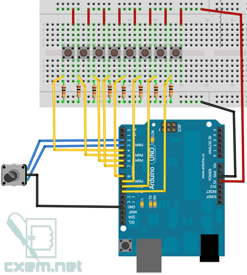
In this article I want to show how you can use an inexpensive Arduino controller to make a simple MIDI keyboard with a USB connection for 8 keys and a scroll wheel.
So I used:
Arduino UNO controller
8 pcs. buttons
8 resistors 10 kOhm
rotary encoder 25LB22-Q
breadboard and jumpers
The connection diagram is as follows:
To connect, I used the simplest option: 1 key - 1 input. However, with a larger number of keys, different controllers, etc. There may not be enough inputs, so you will have to use data reading either through analog inputs (by adding resistors of different values) or through multiplexing. However, if you attach several keys to the analog input, then problems may arise with reading the state when several keys are pressed simultaneously. Therefore, in my opinion, multiplexing is a more acceptable option.
Arduino Software
I will not consider the structure of MIDI data, because... this is described in the article:
The encoder is connected to the hardware interrupt inputs; I will not consider a description of working with it, because The program is simple and taken from the official Arduino website.
In this project, the encoder is used as a scroll wheel to change the modulation wheel, but it can be reassigned for other purposes (pitch bend, etc.).
MIDI data from the encoder, from the Arduino, is sent with the following line:
noteOn(0xB0, 0x01, encoder0Pos);
where 0xB0 is the controller message (control change)
0x01 - controller code (in our case Modulation)
encoder0Pos - controller value (in our case 0-127).
By changing controller codes you can use the scroll wheel (encoder) for a variety of controllers.
Pitch Bend is also worth mentioning. From the MIDI specification it follows that it is necessary to send a message of three bytes: 0xE0 (Pitch Bend code), MSB (high byte), LSB (low byte).
The two outer bytes store a 14-bit pitch value that can range from 0...16383 (0x3FFF). The middle is 0x2000, everything above this value causes the pitch to change upward, if lower, the pitch changes downward.
In the program code, I commented out the lines if you suddenly want to use Pitch Bend instead of modulation (middle of the value, decomposition into 2 bytes, etc.)
The keypress detection code includes three states: a key is pressed, a key is held, and a key is released. This was done so that the value of the duration of a key press could be transmitted. If this is not necessary, then you can leave only one state (key press), the program in this case will be significantly simplified.
To handle the state of each of the eight keys, the following code is used:
If (buttonState_C == HIGH && note_C_send_on == false) // Key pressed ( noteOn(0x90, note_C, 0x7F); note_C_send_on = true; // Note On command sent note_C_send_off = false; // Note Off command not sent ) else if (buttonState_C == HIGH && note_C_send_on == true) // If the key is held ( noteOn(0x00, note_C, 0x7F); note_C_send_on = true; note_C_send_off = false; ) else if (buttonState_C == LOW && note_C_send_off == false) // If the key is released ( noteOn(0x90, note_C, 0x00); note_C_send_on = false; note_C_send_off = true; encoder0Pos = 0; // Return the wheel position to zero ) ....... ....... ... .... // Function for sending a MIDI message to the serial port void noteOn(int cmd, int pitch, int velocity) ( Serial.write(cmd); Serial.write(pitch); Serial.write(velocity); delay( 20); )
Please note that if pitch bend is used, then encoder0Pos will need to be returned not to zero, but to 0x2000 (or it is better to set define at the beginning of the program).
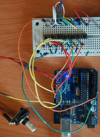
So, the circuit is assembled, the sketch is uploaded to the controller, we launch Serial Monitor, change the transmission speed to 115200 and press the keys or turn the encoder and look at the values.
If everything is fine, then move on to the next part. I’ll say right away that for me it turned out to be the most problematic, and if I had not found a virtual USB -> Midi converter, this article would not have existed.
PC Software (Windows)
In order to receive data via a USB virtual COM port from Arduino and transfer it to any MIDI sequencer program, you need a special utility: Serial MIDI Converter V2D (office site)
The program is multi-platform, it worked for me under Windows 7 x64, although with some problems.
We launch it, select the USB port, baud rate (115200) and MIDI Input Port and MIDI Output Port.
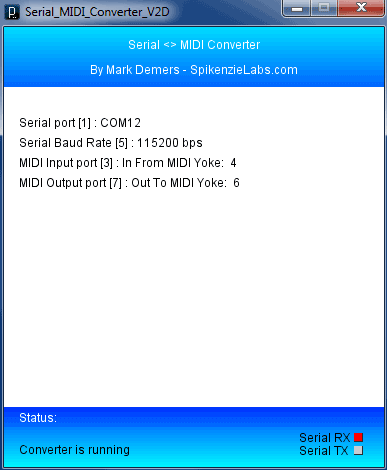
Now, all the MIDI data that comes to the USB virtual COM port 12 is redirected to the MIDI Yoke 6 port (I used the MIDI Yoke program to create virtual MIDI ports). You can redirect them to Microsoft GS Wavetable Synth and other ports.
The program must be turned on at all times. When you press keys or turn the encoder knob, the Serial RX indicator at the bottom should blink.
To visually display incoming MIDI data from the port, I found the MIDI-OX program (office site) very useful:
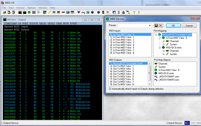
Please note that in the MIDI Devices settings you must set the MIDI Input port.
Now, when you press note keys or turn the wheel, you will see MIDI data in Monitor-Output.
That. With the help of software and hardware, we were able to make a simple MIDI keyboard on the Arduino controller with data transfer to a computer for subsequent processing, for example in Cubase, etc. incl. in real time.
Based on this project, you can make a DJ console, a full-fledged MIDI keyboard, etc.
Below you can download the INO sketch, Serial MIDI Converter V2D, MIDI-OX and MIDI Yoke
