Low frequency generator on one transistor. Audio frequency generator. There are three main types of impulses

Audio frequency generator circuit using transistors
Two transistors - field-effect VT1 and bipolar VT2 - are connected according to a compound repeater circuit, which has a small gain and repeats the phase of the input signal at the output. Deep negative feedback (NFE) through resistors R7, R8 stabilizes both the gain and the mode of the transistors.
But for generation to occur, positive feedback from the amplifier output to its input is also needed. It is carried out through the so-called Wien bridge - a chain of resistors and capacitors R1...R4, C1...C6. The Wien bridge weakens both low (due to the increasing capacitance of capacitors C4...C6) and high (due to the shunting effect of capacitors C1...S3). At the central setting frequency, approximately equal to 1/271RC, its transmission coefficient is maximum, and the phase shift is zero. It is at this frequency that generation occurs.
By changing the resistance of the resistors and the capacitance of the bridge capacitors, the generation frequency can be changed within a wide range. For ease of use, a tenfold range of frequency changes has been selected using dual variable resistors R2, R4, and the frequency ranges are switched (Sla, Sib) by capacitors C1...C6.
To cover all sound frequencies from 25 Hz to 25 kHz Three ranges are enough, but if desired, you can add a fourth, up to 250 kHz (this is what the author did). By choosing slightly larger capacitors or resistor values, you can shift the frequency range down, making it, for example, from 20 Hz to 200 kHz.
The next important point in designing a sound generator is stabilizing the amplitude of the output voltage. For simplicity, the most ancient and reliable method of stabilization is used here - using an incandescent lamp. The fact is that the resistance of the lamp filament increases almost 10 times when the temperature changes from a cold state to full heat! A small-sized indicator lamp VL1 with a cold resistance of about 100 Ohms is included in the OOS circuit. It shunts resistor R6, while the OOS is small, the POS predominates and generation occurs. As the oscillation amplitude increases, the lamp filament heats up, its resistance increases, and the OOS increases, compensating for the POS and thereby limiting the increase in amplitude.
A step divider is switched on at the generator output voltage on resistors R10...R15, allowing you to obtain a calibrated signal with an amplitude from 1 mV to 1 V. The divider resistors are soldered directly to the pins of a standard five-pin connector from audio equipment. The generator receives power from any source (rectifier, battery, battery), often from the same one from which the device under test is powered. The supply voltage on the generator transistors is stabilized by the R11, VD1 chain. It makes sense to replace resistor R11 with the same incandescent lamp as VL1 (telephone indicator, in a “pencil” version) - this will expand the limits of possible supply voltages. Current consumption - no more 15...20 mA.
Parts of almost any type can be used in the generator, but special attention should be paid to the quality of the dual variable resistor R2, R4. The author used a fairly large precision resistor from some outdated equipment, but dual resistors from volume or tone controls on stereo amplifiers will also work. Zener diode VD1 - any low-power one, for stabilization voltage 6.8...9 V.
When setting up, you need to pay attention to the smoothness of generation at approximately the middle position of the trimmer resistor R8 slider. If its resistance is too low, generation may stop in some positions of the frequency setting knob, and if its resistance is too high, distortion of the sinusoidal signal shape may be observed - limitation. You should also measure the voltage at the collector of transistor VT2; it should be equal to approximately half the voltage of the stabilized supply. If necessary, select resistor R6 and, as a last resort, the type and type of transistor YT1. In some cases, it helps to connect in series with an incandescent lamp VL1 an electrolytic capacitor with a capacity of at least 100 µF(“plus” to the source of the transistor). Finally, resistor R10 sets the signal amplitude at the output 1 V and calibrate the frequency scale using a digital frequency meter. It is common for all ranges.
The peculiarity of this sound generator circuit is that everything is built on an ATtiny861 microcontroller and an SD memory card. The Tiny861 microcontroller consists of two PWM generators and, thanks to this, is capable of generating high-quality sound, and is also capable of controlling the generator with external signals. This audio frequency generator can be used to test the sound of high-quality speakers or in simple amateur radio projects such as an electronic bell.
Audio frequency generator circuit on a timer |
The audio frequency generator is built on the popular KP1006VI1 timer microcircuit (almost according to a standard scheme. The output signal frequency is about 1000 Hz. It can be adjusted over a wide range by adjusting the ratings of the radio components C2 and R2. The output frequency in this design is calculated by the formula:
F = 1.44/(R 1 +2×R 2)×C 2
The output of the microcircuit is not capable of providing high power, so a power amplifier is made using a field-effect transistor.

Audio frequency generator on a microcircuit and field switch
Oxide capacitor C1 is designed to smooth out power supply ripples. The SZ capacitance connected to the fifth output of the timer is used to protect the control voltage output from interference.
Any stabilized one with an output voltage from 9 to 15 volts and a current of 10 A will do.
A generator is a self-oscillating system that generates electric current pulses, in which the transistor plays the role of a switching element. Initially, from the moment of its invention, the transistor was positioned as an amplifying element. The presentation of the first transistor took place in 1947. The presentation of the field-effect transistor occurred a little later - in 1953. In pulse generators it plays the role of a switch and only in alternating current generators does it realize its amplifying properties, while simultaneously participating in the creation of positive feedback to support the oscillatory process.
A visual illustration of frequency range division
Classification
Transistor generators have several classifications:
- by frequency range of the output signal;
- by type of output signal;
- according to the operating principle.
The frequency range is a subjective value, but for standardization the following division of the frequency range is accepted:
- from 30 Hz to 300 kHz – low frequency (LF);
- from 300 kHz to 3 MHz – medium frequency (MF);
- from 3 MHz to 300 MHz – high frequency (HF);
- above 300 MHz – ultra-high frequency (microwave).
This is the division of the frequency range in the field of radio waves. There is an audio frequency range (AF) - from 16 Hz to 22 kHz. Thus, wanting to emphasize the frequency range of the generator, it is called, for example, an HF or LF generator. The frequencies of the sound range, in turn, are also divided into HF, MF and LF.
According to the type of output signal, generators can be:
- sinusoidal – for generating sinusoidal signals;
- functional – for self-oscillation of signals of a special shape. A special case is a rectangular pulse generator;
- noise generators are generators of a wide range of frequencies, in which, in a given frequency range, the signal spectrum is uniform from the lower to the upper section of the frequency response.
According to the operating principle of generators:
- RC generators;
- LC generators;
- Blocking generators are short pulse generators.
Due to fundamental limitations, RC oscillators are usually used in the low-frequency and audio ranges, and LC oscillators in the high-frequency range.
Generator circuitry
RC and LC sinusoidal generators
The most simple way to implement a transistor generator is in a capacitive three-point circuit - the Colpitts generator (Fig. below).

Transistor oscillator circuit (Colpitts oscillator)
In the Colpitts circuit, elements (C1), (C2), (L) are frequency-setting. The remaining elements are standard transistor wiring to ensure the required DC operating mode. A generator assembled according to an inductive three-point circuit—the Hartley generator—has the same simple circuit design (Fig. below).

Three-point inductively coupled generator circuit (Hartley generator)
In this circuit, the generator frequency is determined by a parallel circuit, which includes elements (C), (La), (Lb). The capacitor (C) is necessary to create positive AC feedback.
The practical implementation of such a generator is more difficult, since it requires the presence of an inductance with a tap.
Both self-oscillation generators are primarily used in the mid and high frequency ranges as carrier frequency generators, in frequency-setting local oscillator circuits, and so on. Radio receiver regenerators are also based on oscillator generators. This application requires high frequency stability, so the circuit is almost always supplemented with a quartz oscillation resonator.
The master current generator based on a quartz resonator has self-oscillations with a very high accuracy of setting the frequency value of the RF generator. Billions of a percent are far from the limit. Radio regenerators use only quartz frequency stabilization.
The operation of generators in the region of low-frequency current and audio frequency is associated with difficulties in realizing high inductance values. To be more precise, in the dimensions of the required inductor.
The Pierce generator circuit is a modification of the Colpitts circuit, implemented without the use of inductance (Fig. below).

Pierce generator circuit without the use of inductance
In the Pierce circuit, the inductance is replaced by a quartz resonator, which eliminates the time-consuming and bulky inductor and, at the same time, limits the upper range of oscillations.
The capacitor (C3) does not allow the DC component of the base bias of the transistor to pass to the quartz resonator. Such a generator can generate oscillations up to 25 MHz, including audio frequency.
The operation of all of the above generators is based on the resonant properties of an oscillatory system composed of capacitance and inductance. Accordingly, the oscillation frequency is determined by the ratings of these elements.
RC current generators use the principle of phase shift in a resistive-capacitive circuit. The most commonly used circuit is a phase-shifting chain (Fig. below).

RC generator circuit with phase-shifting chain
Elements (R1), (R2), (C1), (C2), (C3) perform a phase shift to obtain the positive feedback necessary for the occurrence of self-oscillations. Generation occurs at frequencies for which the phase shift is optimal (180 degrees). The phase-shifting circuit introduces a strong attenuation of the signal, so such a circuit has increased requirements for the gain of the transistor. A circuit with a Wien bridge is less demanding on transistor parameters (Fig. below).

RC generator circuit with Wien bridge
The double T-shaped Wien bridge consists of elements (C1), (C2), (R3) and (R1), (R2), (C3) and is a narrow-band notch filter tuned to the oscillation frequency. For all other frequencies, the transistor is covered by a deep negative connection.
Functional current generators
Functional generators are designed to generate a sequence of pulses of a certain shape (the shape is described by a certain function - hence the name). The most common generators are rectangular (if the ratio of the pulse duration to the oscillation period is ½, then this sequence is called a “meander”), triangular and sawtooth pulses. The simplest rectangular pulse generator is a multivibrator, which is presented as the first circuit for beginner radio amateurs to assemble with their own hands (Fig. below).

Multivibrator circuit - rectangular pulse generator
A special feature of the multivibrator is that it can use almost any transistors. The duration of the pulses and pauses between them is determined by the values of the capacitors and resistors in the base circuits of transistors (Rb1), Cb1) and (Rb2), (Cb2).
The frequency of self-oscillation of the current can vary from units of hertz to tens of kilohertz. HF self-oscillations cannot be realized on a multivibrator.
Generators of triangular (sawtooth) pulses, as a rule, are built on the basis of generators of rectangular pulses (master oscillator) by adding a correction chain (Fig. below).

Triangular pulse generator circuit
The shape of the pulses, close to triangular, is determined by the charge-discharge voltage on the plates of capacitor C.
Blocking generator
The purpose of blocking generators is to generate powerful current pulses with steep edges and low duty cycle. The duration of pauses between pulses is much longer than the duration of the pulses themselves. Blocking generators are used in pulse shapers and comparing devices, but the main area of application is the master horizontal scan oscillator in information display devices based on cathode ray tubes. Blocking generators are also successfully used in power conversion devices.
Generators based on field-effect transistors
A feature of field-effect transistors is a very high input resistance, the order of which is comparable to the resistance of electronic tubes. The circuit solutions listed above are universal, they are simply adapted for the use of various types of active elements. Colpitts, Hartley and other generators, made on a field-effect transistor, differ only in the nominal values of the elements.
Frequency-setting circuits have the same relationships. To generate HF oscillations, a simple generator made on a field-effect transistor using an inductive three-point circuit is somewhat preferable. The fact is that the field-effect transistor, having a high input resistance, has practically no shunting effect on the inductance, and, therefore, the high-frequency generator will operate more stable.
Noise generators
A feature of noise generators is the uniformity of the frequency response in a certain range, that is, the amplitude of oscillations of all frequencies included in a given range is the same. Noise generators are used in measuring equipment to evaluate the frequency characteristics of the path being tested. Audio noise generators are often supplemented with a frequency response corrector to adapt to subjective loudness for human hearing. This noise is called “gray”.
Video
There are still several areas in which the use of transistors is difficult. These are powerful microwave generators in radar applications, and where particularly powerful high-frequency pulses are required. Powerful microwave transistors have not yet been developed. In all other areas, the vast majority of oscillators are made entirely with transistors. There are several reasons for this. Firstly, the dimensions. Secondly, power consumption. Thirdly, reliability. On top of that, transistors, due to the nature of their structure, are very easy to miniaturize.
A clear advantage in simplicity and stability of operation was shown by the generator according to the circuit proposed (it is simplified in Fig. 1). There, an incandescent lamp, acting as a barter, is connected to the output of a transistor current amplifier to reduce the load on the generator circuit. The same amplifier is provided in the circuit. But it turned out that with an output voltage of 1 V, excluding the amplifier does not affect the parameters of the generator: the lamp filament almost does not heat up, and the amplitude of the output signal practically does not change when the frequency is tuned. Perhaps, with an output voltage of 4 V, the amplifier is useful, but for a master oscillator (MO) there is no need for it. In addition to transistor-based amplifiers, when testing on a breadboard, instead of conventional op-amps, we also tested SSM2135 and SSM2275 microcircuits, which provide a significantly higher output current. In this case, the lamp can heat up without any additional amplifier, but also no difference in amplitude stability and distortion level was noticed. In the generator circuit, the least signal distortion is achieved at a certain optimal output voltage, selected using a trimming resistor. In the generator according to the circuit shown in Fig. 1 in, no regulators are provided, and the amplitude of the output signal can be changed by selecting resistor R3. To obtain a voltage of 1 V, a resistor R3 with a resistance of about 13 kOhm was required.
Increasing the amplitude simultaneously makes it possible to increase the upper limit generation frequency with the same elements. In my opinion, the need to use frequencies above 100 kHz in the practice of audio engineering arises extremely rarely. During experiments, it was discovered that the harmonic distortion coefficient and the output voltage change slightly when replacing the stabilization lamp. Microlamps of optocouplers were used for measurements in the SG prototype. At a frequency of 1 kHz, the following results were obtained: for OEP-2 Kg is 0.11 and 0.068%; for OEP, 23 and 0.095%; for OEP, 1 and 0.12% (two copies each). For several lamps of other types, Kg turned out to be 0.17, 0.081, 0.2 and 0.077%. Measurements have shown that the heating of the filament is extremely small (the resistance of the optocoupler photoresistor practically does not change), although the stabilization of the GB amplitude is very effective. Field-effect transistors stabilize the amplitude of the output signal no worse, but the distortion is greater.
It should be noted that not all op-amps can operate at the highest frequency (100 kHz) in the studied version of the generator. Dual op-amps OP275 or NE5532 can easily provide generation at this frequency, and the SSM2135 microcircuit can generate at frequencies no higher than 92 kHz.
The information on the circuits presented here is quite sufficient for the manufacture of a measuring generator, but for more detailed information and calculation methods, you can refer to the articles.
To obtain a maximum output voltage of about 10 V rms. An output amplifier is required that increases the voltage of the master oscillator by 10 times. In a full-fledged device, you need to control the frequency and voltage of the output signal. The easiest way is to equip the generator with a simple frequency meter and voltmeter. These completely independent devices are placed on separate boards, which facilitated experimental testing of all nodes and eliminated their mutual influence.

The complete circuit of a measuring generator with a frequency meter and a voltmeter is shown in Fig. 2.
The master oscillator (DA1) is assembled on one board, the frequency meter (DA3) is on the second, and the output amplifier and voltmeter (DA2) are on the third. It turns out that the entire device, except for the power supply, is assembled on only three microcircuits, so installation can be easily done on sections of a prototype printed circuit board.
Main technical parameters
Frequency intervals of the generator and frequency meter, Hz, in the subrange
I.......7...110
II......89...1220
III................828...11370
IV......8340...114500
Generator output voltage, V...................0...10
Attenuator attenuation, dB. .10/20/30/40
Output impedance
Ohm.........................100/160
GB harmonic coefficient, %, in the sub-range
I (above 30 Hz) .............0.16
II.........................0.105
III.........................0.065
IV......................0.09
For each of the subranges, the average value of the harmonic coefficient is indicated, which was obtained without any selection of elements (except for the choice of an incandescent lamp) when measuring the signal at the output of the master oscillator. When tuning the frequency, the signal amplitude changed very little.
The master oscillator on the DA2 chip operates in four subranges with slight overlap at the edges. Frequency adjustment is carried out using a dual variable resistor R17. A single resistor can be used for tuning, but the overlap in the sub-range will be significantly less. If there is a built-in frequency meter, there is no need to precisely adjust the range boundaries or ensure a linear change in frequency using group B variable resistors with a nonlinear regulation characteristic. Using the frequency meter scale, the required frequency of the generator signal can be easily set.
Simple analog frequency meters are usually assembled on TTL chips, since they are easier to measure high frequencies. Therefore, some surprises arose when connecting such a frequency meter, which introduced noticeable interference: at a frequency of 100 kHz, the INI showed an increase in the harmonic coefficient to 0.7%. This device uses the K561LA7 (DD1) CMOS chip. The current consumption and interference from the frequency meter are significantly less. To reduce this interference to a minimum, the resistance of the isolation resistor R1 must be selected at least 100 kOhm, then at 100 kHz the value of Kg does not exceed 0.3%. On other ranges, connecting a frequency meter has virtually no effect. To further reduce the level of interference from the frequency meter, a source follower VT1 (KPZZB) is installed at its input.
The operating principle of analog frequency meters is known, and a description of the operation of a monostable can be found in. Switching subranges of the frequency meter is done by the same switch SA1, which switches the generator frequency. If it is possible to select capacitors C2, SZ, C4 and C5 so that their capacitances differ exactly 10 times, then there is no need to install trimming resistors R6-R9.
But you can use capacitors without selection and adjust the readings in each subrange using an external frequency meter (for example, in INI S6-11).
Another surprise was the noticeable nonlinearity of the scale of the microammeters used in the device. Based on availability and aesthetic considerations, the frequency meter uses an M4247 100 µA microammeter, and the voltmeter uses an M4387 300 µA microammeter. Both types of devices were installed in tape recorders to control the signal recording level; they usually have one scale, graduated in decibels. It is clear that special precision was not required here. But with a real reading scale applied measuring instruments of the same type(!) were significantly different either at the beginning or at the end of the scale. However, with a computer and a printer, a new scale can be made very quickly. The difficulty lies in carefully opening the case of the microammeter to install the scale, but this will have to be done, since in a voltmeter, in addition to the usual 10 V scale, you need to have a 3.16 V scale, and for everyone involved in audio engineering it is important to be able to read in decibels. Naturally, nothing prevents the use of other microammeters of a higher class with ready-made scales.
The output stage based on the DA5.2 op-amp (TL082 or TL072), which increases the signal amplitude to 10 V, also slightly increases nonlinear distortion. This cascade differs from that described in only in that switch SA2 “xO,316” is additionally introduced to change the output signal level by 10 dB (set by trimming resistor R30) and button SB1 connected in parallel to it. With the switch contacts open, this button can quickly produce stepwise level changes of 10 dB, which is very convenient when setting up auto level controllers and level meters. The use of the maximum supply voltage (+/-17.5 V) for the amplifier made it possible to obtain a maximum amplitude of the output signal without limitation of at least 10 V. The power supply is equipped with stabilizers with adjustable voltage.
Asymmetrical amplitude limitation can be corrected by adjusting the appropriate supply voltage. The maximum voltage of 10 V at the output connector X1 is set with resistor R31. Then switch SA2 is opened and the voltage is set with trimming resistor R30 exactly 10 dB lower, i.e. 3.16 V. For this, the output voltmeter has a second scale. In the voltage divider, it is necessary to select resistors to ensure an accurate change in the amplitude of the output signal in steps of 20 dB. Sometimes it is enough to simply swap two resistors of the same value in the divider. The advantage of such an attenuator is the constant output impedance of the generator at any output voltage (here 160 Ohms).
Measurements have shown that with an output voltage of 7.75 V at a frequency of 20 Hz, the generator has Kg = 0.27%; and at a voltage of 77 mV (-40 dB) - K = 0.14%. In range II at Uout = 7.75 V Kg<0,16%, в диапазоне III Kr = 0,08...0,09 %. В полосе частот 10...20 кГц при 11ВЫХ = 7,75 В Кг= 0,06 %, а на более высоких частотах возрастал до 0,32 % на частоте 100 кГц. Для обычной эксплуатации прибора это вряд ли имеет значение, хотя возможно подобрать для выходного усилителя другой ОУ. Увы, популярный в звукотех-нической аппаратуре ОУ NE5532 на высокой частоте превращает синусоиду амплитудой 10 В в "пилу".
The entire generator consumes no more than 14 mA from the power source via the +17.5 V circuit, and no more than 18 mA via the -17.5 V circuit, so any low-power device can be used as T1 transformer, providing the required voltages (2x18 V).
The appearance of the device is shown in photo fig. 3. The generator is housed in a plastic case with dimensions of 200x60x170 mm; There are quite a lot of similar cases on sale. The device uses switches PG2-15-4P9NV and toggle switches P1T-1-1V, as well as a button KM1-1. All oxide capacitors, except C8, are for a voltage of 25 V. Output connector X1 - JACK6.3. Operating experience shows how justified the use of such a connector is. First impressions confirm that sometimes this device is more convenient than the GZ-102, and at low frequencies the amplitude stabilization is more stable, and no selection of parts is required. After assembly, you need access to an INI for some time, for example C6-11, for configuration. Using trimmer resistors, you can quickly set instrument readings and check the parameters of the generator. If it turns out that the distortion is large in all subranges, you should select another lamp (we can recommend SMN6.3-20 or similar). For setup, you can use other devices - voltmeters, frequency meters.
To create an instrument scale, you need to draw a linear scale and record voltage readings over the entire tuning range. Then, using a PC, you need to make a new scale taking into account the measured errors and print it using a printer on photo paper. It makes no sense to talk about accuracy here, since it depends on the correctness of the readings of the instruments used for calibration. Now repair and inspection services have been largely abolished; it is now proposed to use certified devices. But certification, although it increases the price of devices, does not in any way affect the accuracy of their readings. Thus, during experiments with generators, three INI S6-11 were used, and their readings were slightly different.
LITERATURE
1. Generator 34 with low nonlinear distortion. - Radio, 1984, No. 7, p. 61.
2. Nevstruev E. Signal generator 34. - Radio, 1989, No. 5, p. 67-69.
3. Petin G. Application of a gyrator in resonant amplifiers and generators. - Radio, 1996, No. 11, p. 33, 34.
4. Biryukov devices based on MOS integrated circuits. - M.: Radio and communication, 1990.
5. Sewed digital chips. - M.: Radio and communication, 1987.
6. Sine wave generator. - Radio, 1995, No. 1, p.45.
Low-frequency generator on transistors, tuning with one resistor.
http://nowradio. *****/generator%20NCH%20na%20tranzistorax%20s%20perestroykoy%20odnim%20rezistorom. htm

Low frequency generator from 18 Hz to 30 KHz. The range is divided into four sub-ranges. To stabilize the output voltage, an AGC system is used. The output voltage level at a load of 15 kOhm is at least 0.5 V. For further use of the generator, you need to use an output stage with low output resistance. For example, an emitter follower with a low-impedance load. The main part of the generator is a three-stage amplifier on transistors T4, T5 and T1 with a transmission coefficient of about 1. The amplifier is covered by negative feedback, the circuit of which includes two phase-shifting stages assembled on transistors T2, T3. Each of them introduces a phase shift, varying from zero to 180° as the frequency changes from zero to infinity. The modulus of the transmission coefficient of these cascades does not depend on the frequency and the introduced phase shift and is close to 1. Thus, at one of the frequencies, which is the quasi-resonant frequency of the generator, the total phase shift introduced by the phase shifter turns out to be equal to 180° and the feedback becomes positive. If the transmission coefficient is sufficient, then the device begins to generate at this frequency. The construction of this generator makes it possible to obtain a fairly high frequency overlap coefficient on subbands (more than 10), however, increasing it beyond 6-8 is impractical due to compression of the frequency scale at the end of the subrange. At high frequencies, the phase shift introduced by the transistors slightly increases the frequency overlap. To stabilize the amplitude of the output signal, an AGC system with a delay is used. The AGC detector is made on diodes D1 and D2, connected to the generator output through an emitter follower on transistor T6. This made it possible to avoid nonlinear distortions by the AGC detector. As the output signal increases, its amplitude turns out to be greater than the opening voltage of diodes D1 and D2. The latter open, and the constant voltage on capacitor C9 increases. As a result, the collector current of transistor T5 increases and, consequently, the collector current of transistor T4 decreases. As a result, the equivalent resistance of the positive feedback decreases, and accordingly the gain decreases, and, consequently, the output signal. The reduction of nonlinear distortions introduced by the AGC system is achieved by negative feedback, which covers cascades on transistors T4 and T5. The AGC delay occurs due to the use of silicon diodes D1, D2 and transistor T5, the base-emitter voltage of which closes diode D1. When setting up the generator, you should use trimming resistor R1 to set the output voltage within 0.5-0.55 V, and use resistors R4 and R9 to achieve minimal nonlinear distortion.
Low frequency generator with Winn bridge
http://*****/NCH%20generator%20s%20mostom%20Vinna%Kgc. htm

By using a Wynne bridge in the feedback circuit, a harmonic oscillation generator can be obtained from a conventional amplifier. Powered by a 9-volt battery (current consumption 10 mA), the generator produces a sinusoidal signal with an amplitude of 1 V in the frequency range from 10 Hz to 140 kHz. The generating part is formed by an operational amplifier OP1 with a positive feedback loop formed by an RC Winn circuit of resistors R3, R4, 100k potentiometers and capacitors C1-C8. The sub-range is selected by a double switch, and smooth adjustment within the sub-range is made by a two-section 100k potentiometer. To maintain a stable amplitude of the output signal, limiting diodes VD1, VD2 and resistor R7 are included in the negative feedback circuit. The second operational amplifier acts as a buffer amplifier, isolating the Wynne circuit from the influence of external load. Using potentiometer VR2, the output signal level is adjusted. The switch positions correspond to the following frequency subranges: "1" - 10Hz; "2" - 100Hz; "3" -1...14 kHz; "4" - 10 kHz. The device is easily mounted on a universal mounting plate and fits into a compact housing.
Radio Parade No. 3 2004 p. 24
The generator produces alternating voltage of symmetrical rectangular, triangular and sinusoidal shapes and is intended for testing and tuning various low-frequency equipment. The simplicity of the circuit and functionality make the generator accessible for repetition. The electrical circuit diagram is shown in the figure.
Sine wave generator
http://nowradio. *****/sinusoidalnuy%20generator%20NCH. htm
The diagram shows a simple sine wave generator made from available elements. Its parameters fully meet the requirements for measuring generators in terms of stability of generated oscillations, nonlinearity, smoothness and stepwise regulation of the output voltage level, low current energy consumption. This generator can be used as a source of low-frequency oscillations when setting up and testing elements of radio receivers, loudspeakers, and to test other measuring instruments.
Main technical characteristics.
Range of generated oscillations, Hz
Coeff. nonlinear distortions no more than, %,
in subranges: 10...40 and 85000Hz 0.8
40...85000 Hz 0.3
Maximum output voltage swing, V 18
Change in output voltage amplitude over the entire range
frequencies no more, dB 0.2
Power consumption no more. W 2

The low-frequency sinusoidal generator on the DA1 chip is made using a Robinson-Wine bridge circuit. The selection of the sub-range (10Hz, 0.1 ..1 kHz, 1 10 kHz, 1 kHz) is carried out by switch SA1, and smooth frequency setting is carried out by dual variable resistor R2. To obtain proportionality between the angle of rotation and the change in frequency, it is necessary that the variable resistor has an exponential characteristic of the change in resistance (group B). The requirements for the identical resistance of each of the two variable resistors are not so high, since small differences can be compensated for by the trimming resistor R7. The negative feedback circuit of the operational amplifier includes a dynamic link consisting of resistor R4 and transistor VT1. The operation of this link has achieved stabilization of the amplitude of the generated oscillations over the entire range. The link is controlled by changing the voltage at the gate of the field-effect transistor, which is supplied from the output of the op-amp. Any change in the output of the DA1 microcircuit causes a change in the resistance of the drain-source channel, and this, in turn, leads to a change in the gain of the cascade. The low-frequency voltage from the output of the first stage is fed through a voltage divider on R10R11 to the non-inverting input of the amplifier on the DA2 chip. The transmission coefficient of this cascade is 10. The DC operation of the cascade is balanced by trimming resistor R12. An attenuator with dB attenuation is connected to the output of the stage. The device is powered from an AC mains through a step-down transformer with an alternating voltage on the secondary winding of 21+21 V. When designing a generator, capacitors C1 - C8 should be selected with a nominal deviation tolerance of no more than 1%, placing them directly between the lamellas of the SA1 biscuit switch. The device is mounted on a printed circuit board made of foil getinax. The generator is configured in the following sequence. An oscilloscope is connected to the common point of resistors R10, R11. Switch SA1 is set to the position of the second sub-band. Trimmer resistors R6 and R7 are used to excite the generator, and by rotating the variable resistor R2, the presence of generation is checked over the entire range of movement of its engine. Then the first sub-range is set, and the variable resistor R2 is set to position 2/3 of the maximum resistance value. By adjusting the adjusted resistors R6 and R7, their position is selected where the sine wave distortion is minimal. To obtain the nonlinear distortion coefficient value specified in the technical specifications, adjustments should be made using a nonlinear distortion meter. A voltmeter with a measurement limit of 0.5...1 V should be connected to the output of the DA2 chip, and the trimmer resistor R12 should be used to balance the operation of the amplifier on the DA2 chip. The regulator for smooth change of the output signal (R11) is calibrated by measuring the voltage directly at the output connector XS1 in the 0 dB attenuator position. By setting sequentially the values 1, 2. 3 V and so on, marks are noted on the regulator scale.
Radio amateur No. 5 2001 p. 22
Function generator 15Hz – 15KHz
http://nowradio. *****/funkcionalnuy%20generator%2015Gc-15Kgc. htm
When setting up low-frequency sound-reproducing equipment, you may need a signal not only of a sinusoidal shape, but also of a rectangular or triangular shape.

The figure shows a diagram of a functional generator that produces sinusoidal, rectangular, and triangular oscillations in the range from 15 Hz to 15 kHz. The entire range is covered without switching by one variable resistor R2. A multivibrator is made on operational amplifiers A1.1 and A1.2. Rectangular pulses are removed from output A1.1. Triangular ones are removed from output A1.2 (via a buffer on A1.4), and to obtain a signal of a shape close to a sinusoidal (parabolic shape), a driver on diodes VD3-VD6 is used, from which the resulting signal is sent to an additional amplifier on A1.4. The power source is on a low-power power transformer T1, with a secondary winding of 5-7V AC. A half-wave rectifier on VD7 and VD8 creates a bipolar voltage, which is stabilized by zener diodes VD1 and VD2. When setting up, the symmetry of a signal close to a sinusoidal shape must be set by selecting resistances R8 or R9. It is advisable to take diodes VD3-VD6 from the same batch.
Radioconstructor No. 9 2008 p. 17
Taken from http://. ru/forum/-info-80795.html
|
|


Important.This FG is from the magazine Radio No. 6 1992 p. 44.
See also “GKCH Lukin 300KHz” and its triangle-sine wave converter.
20. Triangular to sinusoidal voltage converter. http://*****/u2.htm

17. Triangular to sinusoidal voltage converter with sequential approximation.
http://*****/u2.htm

48. Nonlinear sawtooth to sinusoidal voltage converter.

49. Sinusoidal voltage former.

52. Converter of sawtooth voltage to sinusoidal.

A low frequency generator is one of the necessary devices in a radio amateur's laboratory. A wide range of devices for the installation of which this device is needed determines the high level of requirements placed on its parameters. “Recently,” along with classical generator circuits using tunable resonant jRC units as a frequency-setting element, so-called functional generators (FGs) are becoming increasingly widespread. Their advantages include: high stability of the output voltage amplitude; the ability to generate infra-low frequencies; practically zero time to establish the output voltage and frequency; absence of scarce parts in the design (for example, dual precision variable resistors and thermistors). In addition, function generators make it possible to obtain voltage not only of sinusoidal, but also of rectangular and triangular shapes. However, the known circuits of such generators also have a number of disadvantages, the main of which include the relatively high level of nonlinear distortions of the sinusoidal 
signal and limited frequency range in the ultrasonic frequency range.
Rice. 1. Generator circuit diagram
The described function generator, in which these disadvantages are reduced as much as possible, has the following main parameters:
Output voltage shape. ……. Sine, triangular, rectangular
Range of generated frequencies, Hz……0,
Number of subbands………… b
Harmonic coefficient, %:
up to 50 kHz……………o.5
up to 300 kHz…………… 1.0
Unevenness of amplitude-frequency characteristics: %;
up to 50 kHz …………… 1
up to 300 kHz…………… 3
Duration of rectangular voltage fronts, not …………… 250
Maximum double voltage amplitude -
all forms, B…-…………. 10
Maximum load current, mA……. thirty
Division ratios of the output voltage divider, times... .. . …….. 1, 10, 100, 1000
Smooth adjustment of the output voltage amplitude. ………….. At least 1:20
In the function generator circuit, in addition to the main output, there is an additional differential one, the amplitude and shape of the voltage at which are set synchronously with the main one, and the phase shift is 180°. The delay of the signal front at the differential output in relation to the main one is no more than 40 ns. There is also a rectangular pulse output with a level corresponding to TTL logic levels and an adjustable duty cycle ranging from 11 to 10.
The basis of the FG is a closed relaxation system, consisting of an integrator and a comparator and designed to produce oscillations of rectangular and triangular shapes. Time constant of an integrator based on an operational amplifier (op-amp) A1(Fig. 1), and, therefore, the frequency of the generated oscillations depends on the capacitance of one of the capacitors C2...C7, which is connected to the negative feedback circuit using switches S1…S4. The voltage from the integrator output is supplied to the input of a bipolar comparator at the op-amp A2 and upon reaching its triggering threshold, the polarity of the output voltage A2, and consequently, at the input of the integrator it changes to the opposite, and the cycle repeats. Smooth frequency adjustment is carried out by resistor R7.
To convert triangular voltage into sinusoidal voltage, a well-proven functional converter circuit on a field-effect transistor is used, described in detail in. To facilitate the establishment of PG and improve quality indicators, the voltage to the converter is supplied from (the output of a separate scale amplifier A3. Adjusting its gain and zero offset with resistors R22 And R23 allow you to optimize the shape of the triangular voltage supplied to the functional converter on the transistor V8, and significantly improve the shape of the sine wave. The need to introduce an isolation capacitor C8 is determined by the fact that starting from frequencies of several kilohertz at the output of the integrator A1 A shift in the average signal level occurs due to the asymmetry of the comparator response thresholds, which appears at high frequencies. Without capacitor C8 the triangular voltage at the output of the PG becomes asymmetrical relative to zero, and the shape of the sinusoidal signal is sharply distorted.
Triangular voltage output GAS In addition to the functional converter, it is supplied to the input of a Schmitt trigger made on a transistor V10 and microcircuit D.L. Duty cycle of rectangular pulses at the output 8 D1 can be changed by adjusting the trigger threshold with resistor R24.
Voltage of sinusoidal, triangular or rectangular shapes via output waveform switches 55, S6.2 fed to the final scale amplifier A4 and then to a power amplifier using transistors V15, V16. Power supply to op amp A4 fed through RC filters R43C11 And R47C13, preventing possible excitation of the amplifier. A variable resistor is included in the negative feedback circuit of the amplifier R40,. which smoothly regulate the amplitude of the output voltage. This method of regulation, as opposed to turning on a potentiometer at the input of the op-amp, makes the scale of the amplitude regulator uniform for all forms of output voltage and improves the signal-to-noise ratio at low output voltage levels.
A step divider is included at the output of the amplifier, which allows you to attenuate the output signal by 10, 100 or 1000 times. Four division stages are obtained using just two key switches - by simultaneously pressing S7 and S8 The division coefficient is 1000. The advantage of this method is that when the keys are pressed (the division coefficient is 1), the divider resistors are disconnected from the amplifier output, which slightly increases its load capacity in this mode.
The differential output receives voltage from an inverting amplifier similar in circuit to Op-amp A5 and transistors V17, V18. Its input is connected to the output of the first amplifier, and the voltage gain is 1. The differential output voltage divider switches synchronously with the main divider. It is easy to see that the voltage difference between the main and differential outputs is equal to twice the voltage amplitude at each of them. In addition to the possibility of obtaining double the signal amplitude, the presence of a differential output is necessary when setting up a number of devices with a differential input, for example, recorders or differential measuring amplifiers.
ABOUT The role played by relay K1 deserves special mention. The fact is that the edges of rectangular pulses from the output of the comparator, if they are directly connected to the switch S6.2, easily penetrate through its pro-code capacitance to the input of the final amplifier and cause significant distortion of the shape of the triangular and sinusoidal signals. Relay contacts K1, switching circuits having appreciable relative input capacitance A4, they are connected when generating voltages - of the indicated form with a common wire, which completely eliminates this type of distortion.
The generator is powered from any bipolar stabilized power source with a voltage of ±15 V, with low output voltage ripple and a permissible load current of at least 0.15 A. For example, the generator power supply described in can be used. When choosing and setting up a power source, you should pay special attention to eliminating self-excitation of the voltage stabilizer, which is very likely when powering generator circuits.
K574UD1A microcircuits can be replaced with K574UD1B. If you limit the operating frequency of the generator to 30 kHz, it is possible to replace them with K140UD8B, without changing the circuit diagram. Instead of 153UD1, you can use K153UD1 or K553UD1 (with any letter), but in order to obtain a maximum generation frequency of 300 kHz, their selection may be required. At frequencies up to 100 kHz, these types of operational amplifiers operate without selection. When used as A2 For other types of op amps, it is not possible to obtain a generation frequency higher than 50...70 kHz with satisfactory linearity of the frequency response.
As D1 You can use any inverters of the K133, K155 series. Transistors KT315 and KT361 can be replaced with any low-power silicon transistors with appropriate conductivity and similar parameters. If transistors of the KT814, KT815 series (with any letter) are used in power amplifiers, then the load capacity of the generator can be significantly increased. With such a replacement, the resistor values are R53…R56 And R57…R64 should be reduced by about 5 times. Diodes D223 can be replaced with any silicon high-frequency diodes, diodes D311 - D18, GD507, and instead of the transistor KP303E - KP303G or KP303F. Capacitors C2, CS - K53-7 or other non-polar. The remaining capacitors are ceramic types KM, KLS, KTK, etc. You can also use paper capacitors. If the FG is expected to operate in a significant temperature range, it is necessary to select the types of capacitors C2…C7 with small TKE. Preliminary selection of denominations C2…C6 with an accuracy of 1% greatly simplifies setup.
What is a sound generator and what is it used for? So, let's first define the meaning of the word “generator”. Generator – from lat. generator- manufacturer. That is, to explain in everyday language, a generator is a device that produces something. Well, what is sound? Sound- these are vibrations that our ear can discern. Someone farted, someone hiccupped, someone sent someone - all these are sound waves that our ears hear. A normal person can hear vibrations in the frequency range from 16 Hz to 20 Kilohertz. Sound up to 16 Hertz is called infrasound, and the sound is more than 20,000 Hertz - ultrasound.
From all of the above, we can conclude that a sound generator is a device that emits some kind of sound. Everything is elementary and simple;-) Why don’t we assemble it? Scheme to the studio!
As we can see, my circuit consists of:
– capacitor with a capacity of 47 nanoFarads
– resistor 20 Kilohm
– transistors KT315G and KT361G, maybe with other letters or even some other low-power ones
– small dynamic head
- a button, but you can do it without it.
On the breadboard it all looks something like this:
.JPG)
And here are the transistors:
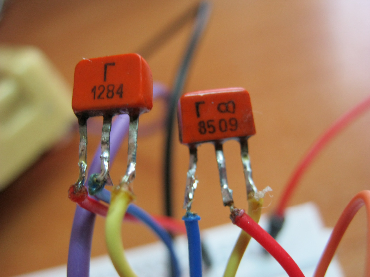
On the left is KT361G, on the right is KT315G. For KT361 the letter is located in the middle of the case, and for 315 it is on the left.
These transistors are complementary pairs to each other.
And here is the video:
The frequency of the sound can be changed by changing the value of the resistor or capacitor. Also, the frequency increases if the supply voltage is increased. At 1.5 Volts the frequency will be lower than at 5 Volts. In my video the voltage is set to 5 Volts.
Do you know what else is funny? Girls have a much greater range of perception of sound waves than boys. For example, guys can hear up to 20 Kilohertz, and girls can even hear up to 22 Kilohertz. This sound is so squeaky that it really gets on your nerves. What do I want to say by this?)) Yes, yes, why don’t we choose resistor or capacitor values such that girls hear this sound, but boys don’t? Just imagine, you are sitting in class, turning on your organ and looking at the dissatisfied faces of your classmates. In order to set up the device, we will of course need a girl to help us hear this sound. Not all girls also perceive this high-frequency sound. But the really funny thing is that it’s impossible to find out where the sound is coming from))). Only if anything, I didn’t tell you that).
Radio amateurs need to receive various radio signals. This requires the presence of a low-frequency and high-frequency generator. Often this type of device is called a transistor generator due to its design feature.
Additional Information. A current generator is a self-oscillating device created and used to generate electrical energy in a network or convert one type of energy into another with a given efficiency.
Self-oscillating transistor devices
The transistor generator is divided into several types:
- according to the frequency range of the output signal;
- by type of signal generated;
- according to the action algorithm.
The frequency range is usually divided into the following groups:
- 30 Hz-300 kHz – low range, designated low;
- 300 kHz-3 MHz – medium range, designated midrange;
- 3-300 MHz – high range, designated HF;
- more than 300 MHz – ultra-high range, designated microwave.
This is how radio amateurs divide the ranges. For audio frequencies, they use the range 16 Hz-22 kHz and also divide it into low, medium and high groups. These frequencies are present in any household sound receiver.
The following division is based on the type of signal output:
- sinusoidal – a signal is issued in a sinusoidal manner;
- functional – the output signals have a specially specified shape, for example, rectangular or triangular;
- noise generator – a uniform frequency range is observed at the output; ranges may vary depending on consumer needs.
Transistor amplifiers differ in their operating algorithm:
- RC – main area of application – low range and audio frequencies;
- LC – main area of application – high frequencies;
- Blocking oscillator - used to produce pulse signals with high duty cycle.

Picture on electrical diagrams
First, let's consider obtaining a sinusoidal type of signal. The most famous oscillator based on a transistor of this type is the Colpitts oscillator. This is a master oscillator with one inductance and two series-connected capacitors. It is used to generate the required frequencies. The remaining elements provide the required operating mode of the transistor at direct current.
Additional Information. Edwin Henry Colpitz was the head of innovation at Western Electric at the beginning of the last century. He was a pioneer in the development of signal amplifiers. For the first time he produced a radiotelephone that allowed conversations across the Atlantic.
The Hartley master oscillator is also widely known. It, like the Colpitts circuit, is quite simple to assemble, but requires a tapped inductance. In the Hartley circuit, one capacitor and two inductors connected in series produce generation. The circuit also contains an additional capacitance to obtain positive feedback.

The main area of application of the devices described above is medium and high frequencies. They are used to obtain carrier frequencies, as well as to generate low-power electrical oscillations. Receiving devices of household radio stations also use oscillation generators.
All of the listed applications do not tolerate unstable reception. To do this, another element is introduced into the circuit - a quartz resonator of self-oscillations. In this case, the accuracy of the high-frequency generator becomes almost standard. It reaches millionths of a percent. In receiving devices of radio receivers, quartz is used exclusively to stabilize reception.
As for low-frequency and sound generators, there is a very serious problem here. To increase the tuning accuracy, an increase in inductance is required. But an increase in inductance leads to an increase in the size of the coil, which greatly affects the dimensions of the receiver. Therefore, an alternative Colpitts oscillator circuit was developed - the Pierce low-frequency oscillator. There is no inductance in it, and in its place a quartz self-oscillation resonator is used. In addition, the quartz resonator allows you to cut off the upper limit of oscillations.
In such a circuit, the capacitance prevents the constant component of the base bias of the transistor from reaching the resonator. Signals up to 20-25 MHz, including audio, can be generated here.
The performance of all the devices considered depends on the resonant properties of the system consisting of capacitances and inductances. It follows that the frequency will be determined by the factory characteristics of the capacitors and coils.
Important! A transistor is an element made from a semiconductor. It has three outputs and is capable of controlling a large current at the output from a small input signal. The power of the elements varies. Used to amplify and switch electrical signals.
Additional Information. The presentation of the first transistor was held in 1947. Its derivative, the field-effect transistor, appeared in 1953. In 1956 The Nobel Prize in Physics was awarded for the invention of the bipolar transistor. By the 80s of the last century, vacuum tubes were completely forced out of radio electronics.
Function transistor generator
Functional generators based on self-oscillation transistors are invented to produce methodically repeating pulse signals of a given shape. Their form is determined by the function (the name of the entire group of similar generators appeared as a result of this).
There are three main types of impulses:
- rectangular;
- triangular;
- sawtooth.
A multivibrator is often cited as an example of the simplest LF producer of rectangular signals. It has the simplest circuit for DIY assembly. Radio electronics engineers often begin with its implementation. The main feature is the absence of strict requirements for the ratings and shape of transistors. This occurs due to the fact that the duty cycle in a multivibrator is determined by the capacitances and resistances in the electrical circuit of transistors. The frequency on the multivibrator ranges from 1 Hz to several tens of kHz. It is impossible to organize high-frequency oscillations here.
Obtaining sawtooth and triangular signals occurs by adding an additional circuit to a standard circuit with rectangular pulses at the output. Depending on the characteristics of this additional chain, rectangular pulses are converted into triangular or sawtooth pulses.
Blocking generator
At its core, it is an amplifier assembled on the basis of transistors arranged in one cascade. The scope of application is narrow - a source of impressive, but transient in time (duration from thousandths to several tens of microseconds) pulse signals with large inductive positive feedback. The duty cycle is more than 10 and can reach several tens of thousands in relative values. There is a serious sharpness of the fronts, practically no different in shape from geometrically regular rectangles. They are used in the screens of cathode-ray devices (kinescope, oscilloscope).
Pulse generators based on field-effect transistors
The main difference between field-effect transistors is that the input resistance is comparable to the resistance of electronic tubes. Colpitts and Hartley circuits can also be assembled using field-effect transistors, only the coils and capacitors must be selected with the appropriate technical characteristics. Otherwise, field-effect transistor generators will not work.
The circuits that set the frequency are subject to the same laws. For the production of high-frequency pulses, a conventional device assembled using field-effect transistors is better suited. The field effect transistor does not bypass the inductance in the circuits, so the RF signal generators operate more stably.
Regenerators
The LC circuit of the generator can be replaced by adding an active and negative resistor. This is a regenerative way to obtain an amplifier. This circuit has positive feedback. Thanks to this, losses in the oscillatory circuit are compensated. The described circuit is called regenerated.
Noise generator
The main difference is the uniform characteristics of low and high frequencies in the required range. This means that the amplitude response of all frequencies in this range will not be different. They are used primarily in measurement equipment and in the military industry (especially aircraft and rocketry). In addition, the so-called “gray” noise is used to perceive sound by the human ear.
Simple DIY sound generator
Let's consider the simplest example - the howler monkey. You only need four elements: a film capacitor, 2 bipolar transistors and a resistor for adjustment. The load will be an electromagnetic emitter. A simple 9V battery is enough to power the device. The operation of the circuit is simple: the resistor sets the bias to the base of the transistor. Feedback occurs through the capacitor. The tuning resistor changes the frequency. The load must have high resistance.

With all the variety of types, sizes and designs of the considered elements, powerful transistors for ultra-high frequencies have not yet been invented. Therefore, generators based on self-oscillation transistors are used mainly for the low and high frequency ranges.
Video
